Eureka AIR delivers breakthrough ideas for toughest innovation challenges, trusted by R&D personnel around the world.

Visual-locating laser marking system correcting method

A technology of laser marking and visual positioning, which is applied in laser welding equipment, welding equipment, metal processing equipment, etc., can solve the problems of inability to reflect real-time marking adjustment results, achieve lower precision requirements, high calibration precision, and improve system precision Effect

Active Publication Date: 2017-12-19
HUBEI SANJIANG AEROSPACE HONGFENG CONTROL
View PDF3 Cites 10 Cited by
  • Summary
  • Abstract
  • Description
  • Claims
  • Application Information

AI Technical Summary

Problems solved by technology

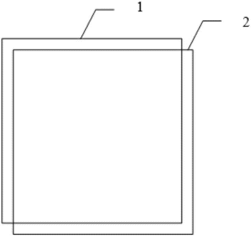
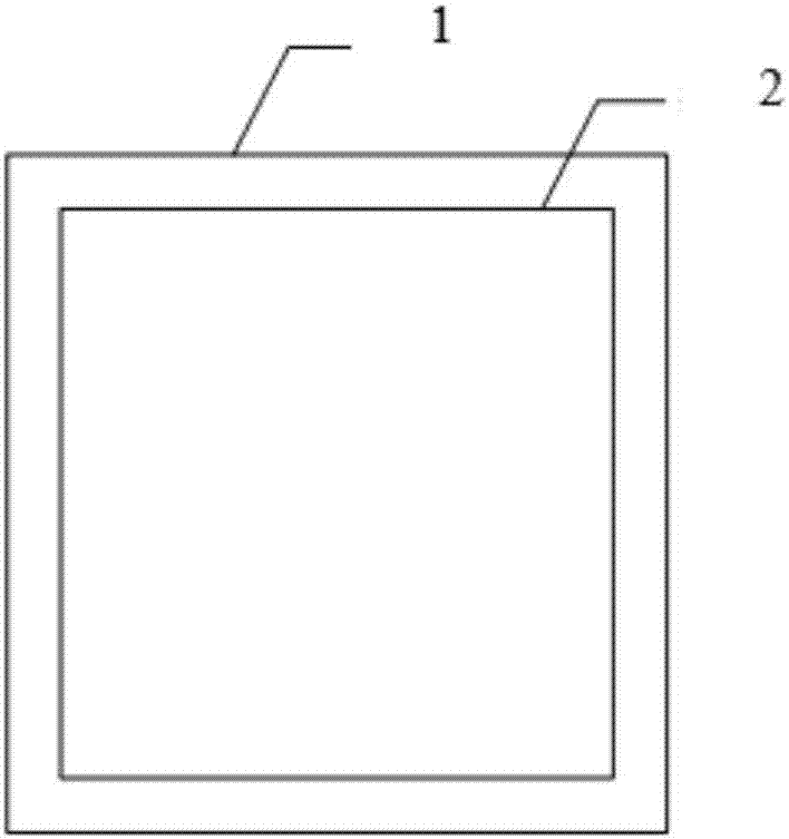
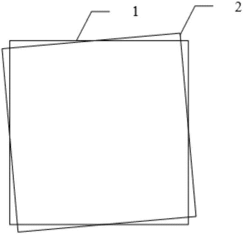
The method of the technical solution of the present invention aims at the situation in the prior art that the display image only displays the current image content, and cannot be reflected on the display image in real time according to the marking adjustment result. Calibration can realize the integration of image display and marking objects, so that the marking adjustment results can be reflected on the image display in real time

Method used


Image

  • Visual-locating laser marking system correcting method
  • Visual-locating laser marking system correcting method
  • Visual-locating laser marking system correcting method

Examples


Embodiment Construction

[0041] In order to make the object, technical solution and advantages of the present invention clearer, the present invention will be further described in detail below in conjunction with the accompanying drawings and embodiments. It should be understood that the specific embodiments described here are only used to explain the present invention, not to limit the present invention. In addition, the technical features involved in the various embodiments of the present invention described below can be combined with each other as long as they do not constitute a conflict with each other. The present invention will be further described in detail below in combination with specific embodiments.

[0042] The correction method of the visual positioning laser marking system of the present invention is realized through multiple steps. like figure 2 Shown is a flow chart of the calibration method for the visual positioning laser marking system in the embodiment of the technical solution...


PUM


Abstract

The invention discloses a visual-locating laser marking system correcting method. The method comprises the following steps that a galvanometric scanner is corrected, so that the laser marking effect is not distorted; the marking coordinate scaling multiple and the galvanometric scanner deflection angle are adjusted, and therefore image display can be obtained, wherein a marking object serves as a reference, and the image display is completely consistent with the marking object; a to-be-corrected marking region is determined on the marking object, the position of the marking object is compared with that of the image display, a clipping starting point of a to-be-corrected display region is determined, the position of the to-be-corrected display region is adjusted to enable the position of the to-be-corrected marking region to be completely consistent with that of the to-be-corrected display region, and therefore integrated display of the clipped to-be-corrected display region and the clipped to-be-corrected marking region is achieved finally. According to the visual-locating laser marking system correcting method, the defects that in the prior art, the correction manner is low in accuracy, and the personnel workload is large are overcome, and the marking object and image display integrated display manner is adopted, so that high-accuracy correction of a marking system and an image system is achieved, and the visual-locating marking accuracy requirements of all the current industries can be met.

Description

technical field [0001] The invention belongs to the field of laser equipment technology and vision correction, in particular to a correction method for a visual positioning laser marking system. Background technique [0002] Adding vision technology to the traditional laser marking system is the general trend of the intelligent development of laser equipment, and it is also an urgent need for modern automated production. The ideal visual positioning marking system is composed of image display and marking functions integrated, combined with image processing technology, it can not only "see", but also "think", which can effectively solve the problem of batch irregular marking Problems such as difficult material supply, poor positioning, and slow speed caused by difficulties in the design and manufacture of middle fixtures. In the actual system construction process, due to the inevitable errors in the optical path and structural installation, as well as the random errors gener...

Claims


Application Information

Patent Timeline
Patent Type & Authority Applications(China)
IPC IPC(8): B23K26/362B23K26/70
CPCB23K26/361B23K26/702
Inventor 周杰王晓通
Owner HUBEI SANJIANG AEROSPACE HONGFENG CONTROL
Why Eureka
Eureka Blog
Learn More