An electromechanical braking device

An electro-mechanical brake and brake caliper technology, applied in mechanical equipment, brake actuators, gear shifting mechanisms, etc. The effect of fast response to requirements, large transmission ratio, and improved response speed

Inactive Publication Date: 2019-05-10
PUYANG VOCATIONAL & TECHN COLLEGE
View PDF6 Cites 0 Cited by
  • Summary
  • Abstract
  • Description
  • Claims
  • Application Information

AI Technical Summary

Problems solved by technology

However, in the existing electronic mechanical braking system, the structure of the braking device is complicated, it takes up a large space, and the manufacturing cost is high, so it is difficult to realize the application of loading in the actual use

Method used


Image

  • An electromechanical braking device

Examples


Embodiment Construction

[0015] A specific embodiment of the present invention will be described in detail below in conjunction with the accompanying drawings, but it should be understood that the protection scope of the present invention is not limited by the specific embodiment.

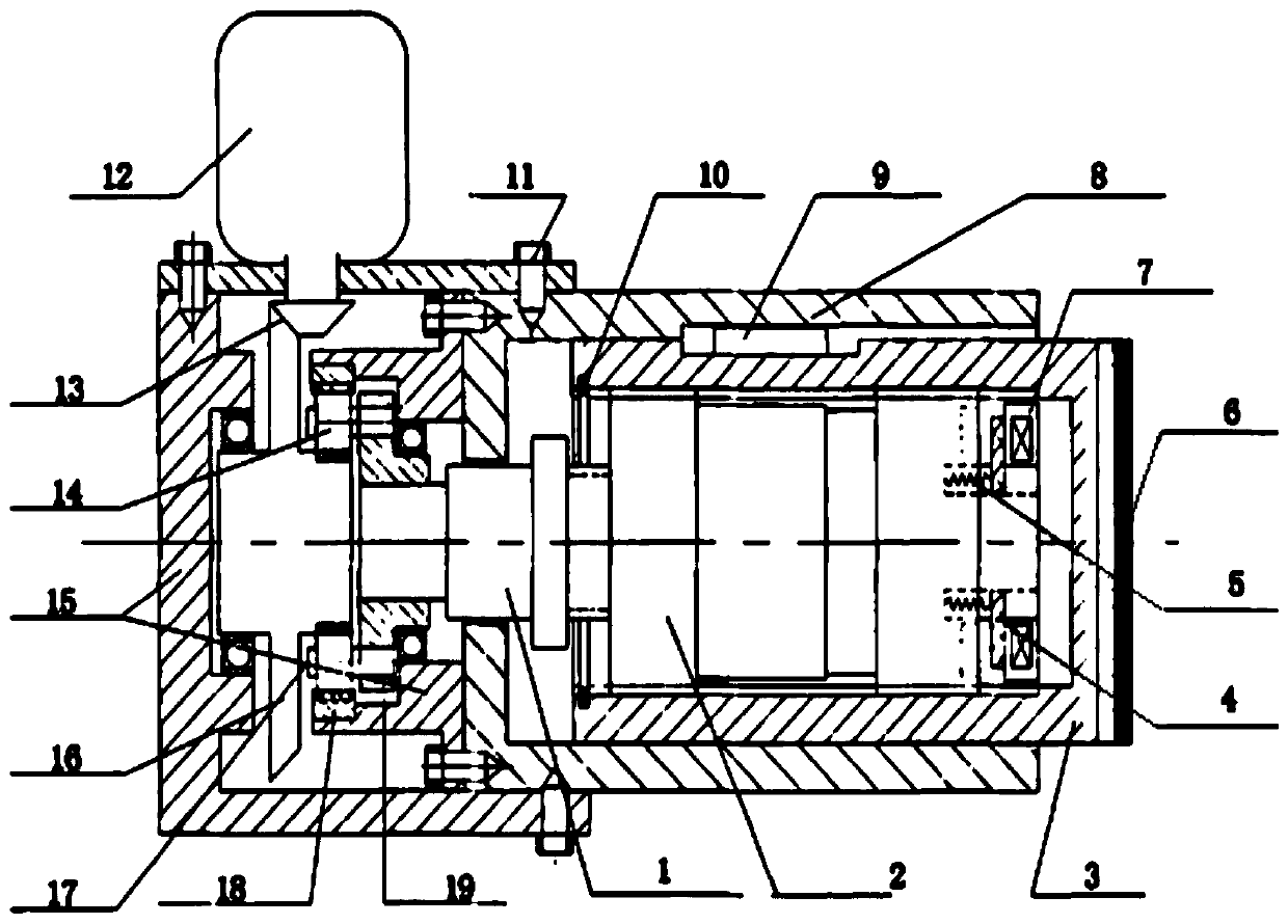
[0016] Such as figure 1 As shown, the embodiment of the present invention provides an electromechanical braking device, including a brake caliper body 8, a ball screw 1 is arranged inside the brake caliper body 8, and balls are sleeved on the ball screw 1. A screw nut 2, the ball screw nut 2 is sleeved with a sliding screw nut 3; the right end of the ball screw nut 2 is symmetrically arranged with a pair of springs 5 ​​along its axial direction, and the other end of the spring 5 is connected with Armature 4; the armature 4 is matched with the electromagnetic clutch 7 arranged on the right side of the ball screw nut 2; the left side of the brake caliper body 8 is connected with a box body 15 through a screw 11, and the top ...


PUM


Abstract

The invention discloses an electronic mechanical brake device. The device comprises a brake clamp body, a ball screw is arranged in the brake clamp body, and is sleeved with a ball screw nut, the ball screw nut is sleeved with a sliding screw nut, a pair of springs are symmetrically arranged at the right end of the ball screw nut in the axial direction, the other ends of the springs are connected with an armature, the armature is matched with an electromagnetic clutch on the right side of the ball screw nut, the left side of the brake clamp body is connected with a box body through a screw, a motor is arranged above the box body, a spiral bevel gear is connected to an output shaft of the motor, a planet gear is connected to the lower portion of the spiral bevel gear, and a sun gear in the planet gear is rotatably connected with the left end of the ball screw. According to the device, through a ball screw nut pair and a sliding nut screw pair, traveling and parking can be comprehensively achieved, the traveling brake time can be shortened, meanwhile, the parking self-locking problem can be ingeniously solved, and the whole structure is compact and concentrated.

Description

technical field [0001] The invention relates to the field of automobile automatic technology, in particular to an electromechanical braking device. Background technique [0002] As consumers place increasing emphasis on vehicle safety, vehicle braking systems have undergone several changes and improvements. From the initial leather friction brake, to the appearance of drum and disc brakes, and then to the appearance of mechanical ABS braking system, followed by the development of electronic technology, analog electronic ABS braking system and digital electronic control system appeared. ABS braking system and so on. In the past 10 years, western developed countries have started to study the x-by-wire vehicle system, and then started the research on the electromechanical brake by the brake-by-wire system. Simply put, the electromechanical brake is to change the part of the brake system that was originally driven by hydraulic pressure or compressed air to be driven by an elec...

Claims


Application Information

Patent Timeline
Patent Type & Authority Patents(China)
IPC IPC(8): F16D65/14F16D121/20F16D121/14F16D121/24
CPCF16D65/14F16D2121/14F16D2121/20F16D2121/24
Inventor 苗英恺
Owner PUYANG VOCATIONAL & TECHN COLLEGE
Why Eureka
Try Eureka