Conveying and drying device for grain drying machine

A grain dryer and drying device technology, applied in the direction of dryer, drying, drying gas arrangement, etc., can solve the problems of time-consuming, inconvenient transportation, etc., and achieve the goals of avoiding mildew, reducing volume and rational application Effect

Inactive Publication Date: 2017-12-19
合肥横冲机械科技有限公司
View PDF7 Cites 5 Cited by
  • Summary
  • Abstract
  • Description
  • Claims
  • Application Information

AI Technical Summary

Problems solved by technology

[0003] The purpose of the present invention is to provide a conveying drying device for a grain dryer, which can be dried by conveying hot air through a splitter box installed between two pulleys, which solves the problem that the drying process of the existing dryer takes a long time and is not convenient for transportation And other issues

Method used


Image

  • Conveying and drying device for grain drying machine
  • Conveying and drying device for grain drying machine
  • Conveying and drying device for grain drying machine

Examples


Embodiment Construction

[0021] The following will clearly and completely describe the technical solutions in the embodiments of the present invention with reference to the accompanying drawings in the embodiments of the present invention. Obviously, the described embodiments are only some, not all, embodiments of the present invention. Based on the embodiments of the present invention, all other embodiments obtained by persons of ordinary skill in the art without creative efforts fall within the protection scope of the present invention.

[0022] In describing the present invention, it is to be understood that the terms "opening", "upper", "lower", "thickness", "top", "middle", "length", "inner", "surrounding" etc. Indicating orientation or positional relationship is only for the convenience of describing the present invention and simplifying the description, and does not indicate or imply that the components or elements referred to must have a specific orientation, be constructed and operated in a sp...


PUM


Abstract

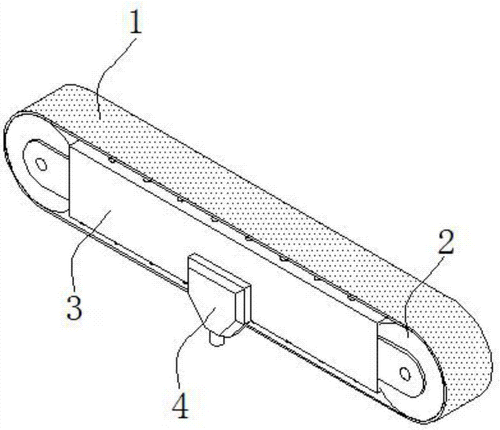
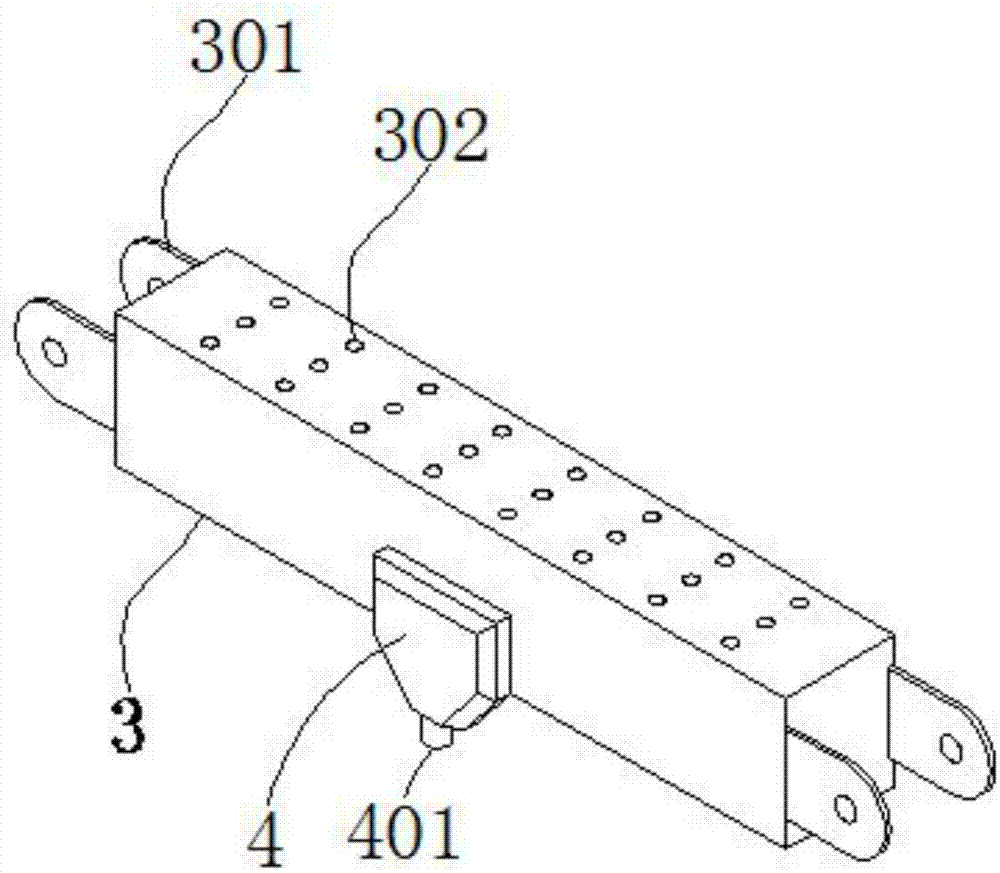
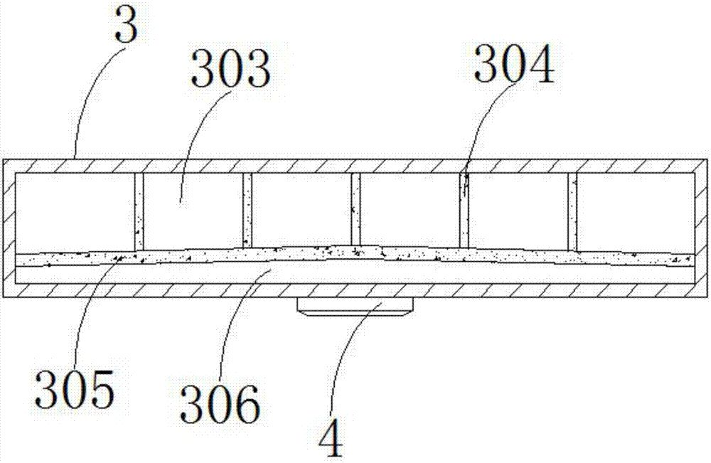
The invention discloses a conveying and drying device for a grain drying machine, and relates to the technical field of conveying equipment. The conveying and drying device comprises a conveying belt, belt wheels and a diversion box; a group of suspension loops is arranged on each of the opposite end faces of the diversion box; a plurality of through holes are formed in one side surface of the diversion box; an air inlet disc is arranged on the other side surface of the diversion box; an air inlet is formed in one side surface of the air inlet disc; each belt wheel is arranged between the corresponding suspension loops; the conveying belt is arranged on the outer sides of the belt wheels and the diversion box; the diversion box comprises partition plates and a guide plate; the partition plates are fixed between the inner wall of the diversion box and the guide plate, thus first cavities are formed; and a second cavity is formed between the inner wall of the diversion box and the guide plate. Hot air is conveyed for drying through the diversion box arranged between the two belt wheels, so that the discharge amounts of the hot air of the through holes in different positions are the same, and the cross section of the guide plate is V-shaped, so that air pressure of different diversion holes is the same, and mildewing caused by the fact that the degree of drying of grain is not consistent is avoided.

Description

technical field [0001] The invention belongs to the technical field of conveying equipment, in particular to a conveying and drying device for a grain dryer. Background technique [0002] The existing grain drying machine is equipped with multiple drying chambers that can dry various grains at the same time. The multiple drying chambers are arranged side by side. Each drying chamber is surrounded by a ventilating plate with mesh. Multiple drying chambers in the dryer body The body shares a heat recovery room and a ventilation channel. The heat recovery room is arranged in parallel above the ventilation channel. The bottom surface of the ventilation channel is open and directly communicates with each drying warehouse body; The air duct is externally connected to a cooling fan. It takes a long time in the drying process, which is inconvenient for later transportation. In addition, the equipment is large in size and inconvenient for transportation. Contents of the invention ...

Claims


Application Information

Patent Timeline
Patent Type & Authority Applications(China)
IPC IPC(8): F26B21/00F26B25/00A23B9/08
CPCA23B9/08F26B21/004F26B25/002F26B2200/06
Inventor 李林红
Owner 合肥横冲机械科技有限公司
Why Eureka
Try Eureka