A kind of sealing method of on-cell product and its binding area

An ON-CELL, binding area technology, applied in the sealing field of ON-CELL products and their binding areas, can solve problems such as poor sealing, and achieve the effect of extending service life, avoiding product defects, and enhancing reliability.

Active Publication Date: 2020-08-04
CHANGSHA YUSHUN DISPLAY TECH +3
View PDF6 Cites 0 Cited by
  • Summary
  • Abstract
  • Description
  • Claims
  • Application Information

AI Technical Summary

Problems solved by technology

[0004] The purpose of the present invention is to provide a sealing method for ON-CELL products and their binding areas, which enhances the sealing effect on the binding areas of ON-CELL products, and solves the problem of poor sealing performance caused by the inability of ON-CELL products to be glued.

Method used


Image

  • A kind of sealing method of on-cell product and its binding area
  • A kind of sealing method of on-cell product and its binding area

Examples


Embodiment 1

[0041] Example 1, such as figure 2 As shown, the sealing method of a kind of ON-CELL product binding area of ​​the first embodiment of the present invention comprises:

[0042] Step 1, prepare TFT upper glass 1 and TFT lower glass 2, and the width of TFT lower glass 2 is greater than the width of TFT upper glass 1;

[0043] Step 2, attaching a lower polarizer 4 on the lower surface of the TFT lower glass 2;

[0044] Step 3, cleaning the terminals of the TFT lower glass 2, binding the driving integrated circuit IC5 on the upper surface of the TFT lower glass 2, and the driving integrated circuit IC5 is not in contact with the TFT upper glass 1;

[0045] Step 4, bind the lower glass binding pins on the upper surface of the TFT lower glass 2, bind the lower glass FPC6 to the lower glass binding pins, and the driving integrated circuit IC5 is not in contact with the lower glass FPC6;

[0046] Step 5: Clean the terminals of TFT upper glass 1, bind the upper glass binding pins on...

Embodiment 2

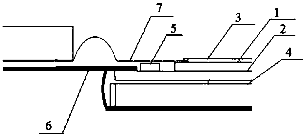
[0065] Embodiment 2, a kind of ON-CELL product described in the embodiment of the present invention, such as figure 2 shown, including:

[0066] TFT lower glass 2, lower polarizer 4 arranged on the lower surface of TFT lower glass 2, driving integrated circuit IC5 bound to the upper surface of TFT lower glass 2, lower glass binding pins bound to the upper surface of TFT lower glass 2 , the lower glass FPC6 bound to the lower glass binding pin;

[0067] TFT upper glass 1, upper polarizer 3 arranged on the upper surface of TFT upper glass 1, upper glass binding pins bound on the upper surface of TFT upper glass 1, upper glass FPC7 bound on the upper glass binding pins ;

[0068] The width of TFT lower glass 2 is greater than that of TFT upper glass 1;

[0069] The sealing line glue provided at the upper glass binding pin and the lower glass binding pin;

[0070] A sealing material provided between the end of the upper polarizer 3 and the end of the upper glass FPC7.

[007...


PUM


Abstract

The invention discloses a sealing method for a bound region in an ON-CELL product. The method comprises the steps of preparing TFT upper glass and TFT lower glass, wherein the TFT lower glass is wider than the TFT upper glass; attaching a lower polarizer to the lower surface of the TFT lower glass; binding a driver integrated circuit (IC) to the upper surface of the TFT lower glass, wherein the driver IC is not in contact with the TFT upper glass; binding a lower glass binding pin to the upper surface of the TFT lower glass, and binding a lower glass FPC to the lower glass binding pin, wherein the driver IC is not in contact with the lower glass FPC; binding an upper glass binding pin to the upper surface of the TFT upper glass, and binding an upper glass FPC to the upper glass binding pin, wherein the driver IC is not in contact with the upper glass FPC; and attaching an upper polarizer to the upper surface of the TFT upper glass, wherein the width of the upper polarizer is greater than the length of the lower polarizer, and the end part of the upper polarizer covers the end part of the upper glass FPC. The method has the beneficial effects that the sealing effect of the bound region in the ON-CELL product is enhanced; and the problem of poor sealing property caused by the fact that line glue cannot be applied to the ON-CELL product is solved.

Description

technical field [0001] The invention relates to the technical field of touch display, in particular to an ON-CELL product and a sealing method for its binding area. Background technique [0002] At present, the most important development direction of the whole machine is light and thin, the lighter and thinner the more convenient to carry, the visual requirements are getting higher and higher, such as narrow bezel technology; the ON-CELL technology dominated by the TFT display panel industry has become the mainstream technology of competition. [0003] In the whole capacitive touch screen manufacturing process, the quality of dispensing in the bonding area will directly affect the service life of the product. The water vapor and impurities that appear during production and use will gradually corrode the bonding area, causing abnormalities in the connection of the gold fingers in the bonding area, and even oxidation, corrosion, and fracture. This causes a great reliability r...

Claims


Application Information

Patent Timeline
IPC IPC(8): G06F3/041G06F3/044
CPCG06F3/0412G06F3/044G06F2203/04103
Inventor 唐志祥黄效牛徐涛涛冯佑胜佘光全姚勇
Owner CHANGSHA YUSHUN DISPLAY TECH
Why Eureka
Try Eureka