electrical connector

A technology of electrical connectors and connecting parts, which is applied in the direction of connection and connection device components, circuits, etc., which can solve the problem of unstable contact between grounding terminals and shrapnel, affecting the signal integrity of electrical connectors, and unstable effects of ground mode resonance and other problems to achieve the effect of avoiding poor contact, avoiding bad products, and improving life

Active Publication Date: 2020-12-22
DEYI PRECISION ELECTRONIC IND CO LTD PANYU
View PDF3 Cites 0 Cited by
  • Summary
  • Abstract
  • Description
  • Claims
  • Application Information

AI Technical Summary

Problems solved by technology

[0003] However, the ground terminal has different geometric shapes at different positions and the surrounding medium is different at different positions, which leads to the inability to maintain zero potential difference between adjacent positions of the ground terminal, and different potentials at different positions , There are also different potentials between multiple ground loops, which makes the ground terminal carry undesired transmission modes. These undesired transmission modes mainly appear as ground mode resonance on the ground terminal, and ground mode resonance will cause insertion loss. The sharp corner of the curve will also cause a sudden change in the impedance of the terminal, which will affect the signal integrity of the electrical connector
[0004] In the known technology, in order to reduce the resonance of the ground mode, a metal ground bridge is generally used, and a plurality of shrapnels are formed on the metal ground bridge to abut against multiple ground terminals respectively, and the multiple ground terminals are connected together to reduce the electrical resistance of the ground terminals. Length, so as to reduce the resonance of the ground mode, but the contact effect between the metal ground bridge and the ground terminal is affected by the installation process and material characteristics, resulting in metal fatigue, wear, bending and other undesirable phenomena of the shrapnel, or dust, water vapor If impurities enter between the ground terminal and the shrapnel, the above-mentioned adverse phenomena will make the contact between the ground terminal and the shrapnel unstable, thus affecting the resonance of the ground mode unstable and affecting the signal integrity of the electrical connector

Method used


Image

  • electrical connector
  • electrical connector
  • electrical connector

Examples


Embodiment Construction

[0033]In order to facilitate a better understanding of the purpose, structure, features, and effects of the present invention, the present invention will now be further described with reference to the drawings and specific embodiments.

[0034]The up and down direction in this specification is the Z axis in the drawings of the specification, the direction of the Z axis arrow is upwards, the front and back direction is the X axis in the drawings of the specification, the direction of the X axis arrow is forward, and the left and right directions are in the drawings of the specification. The Y axis of the Y axis, the arrow of the Y axis points to the right.

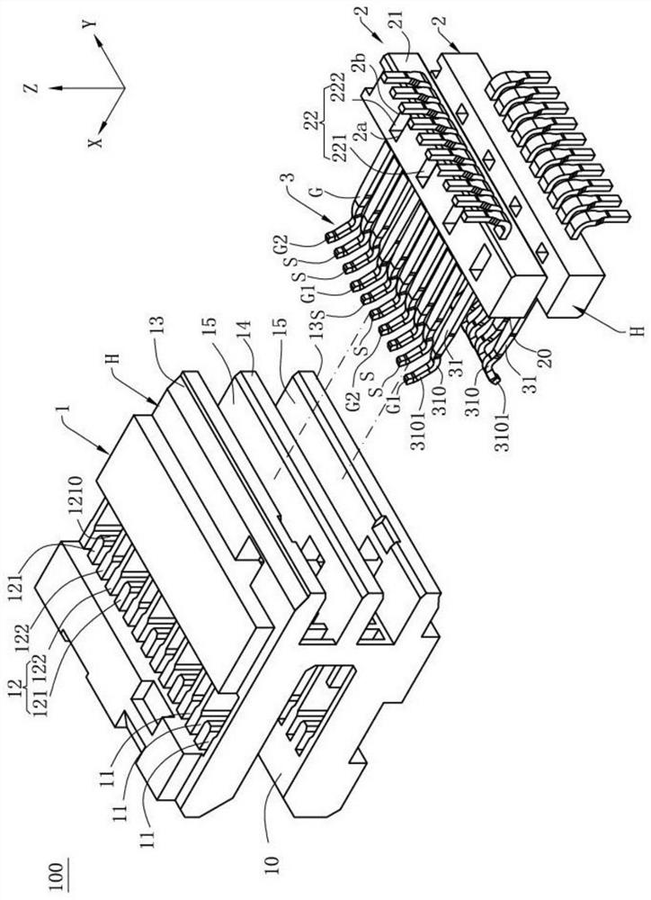
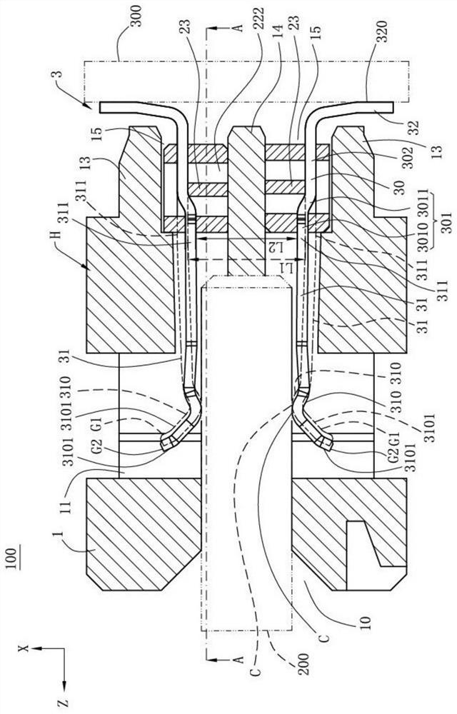
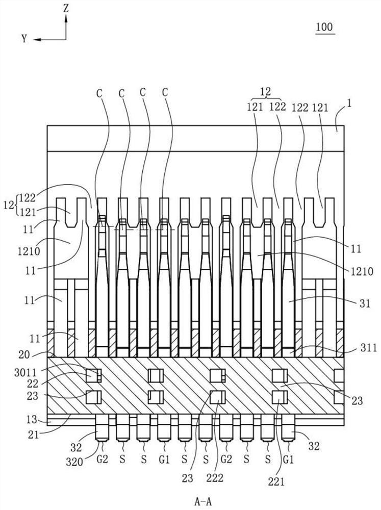
[0035]Seefigure 1 ,figure 2 withimage 3 , This is an electrical connector 100 according to a specific embodiment of the present invention, which electrically connects a first electronic component 200 and a second electronic component 300. The first electronic component 200 may be a docking connector, an electronic card or a flexible ci...


PUM


Abstract

The invention discloses an electric connector. The electric connector comprises a shell provided with a butt joint groove for accommodating a first electronic element and a fixed block, wherein the fixed block is provided with a front surface; and a row of terminals arranged on one side of the butt joint groove. Each terminal is provided with a middle part fixed in the fixed block and an extensionarm extending out of the front surface. The middle part is provided with a first part connected with the extension arm and a second part extending backwards from the first part. A connecting part connected with the front surface is arranged at the rear end of the extension arm. The terminals comprise a pair of signal terminals, and first grounding terminals and second grounding terminals, whereinthe first grounding terminals and the second grounding terminals are arranged on two adjacent sides of the pair of signal terminals. The second parts of the first grounding terminals, the second parts of the pair of signal terminals and the second parts of the second grounding terminals are located at the same height. The connecting part of the first grounding terminals and the connecting part ofthe adjacent signal terminals are located at the same height, and the connecting part of the second grounding terminal and the connecting part of the adjacent signal terminals are located at different heights.

Description

【Technical Field】[0001]The invention relates to an electrical connector, in particular to a connector with good signal integrity.【Background technique】[0002]An electrical connector with an insulating body. The insulating body has a row of terminals. A row of terminals consists of multiple pairs of differential signal terminals and multiple ground terminals alternately arranged at intervals. The ground terminals form a signal ground loop to shield the differential signal terminals effect.[0003]However, the grounding terminal has different geometries at different positions and the surrounding medium is not the same at different positions, which leads to the inability to maintain a zero potential difference between adjacent positions of the grounding terminal, and different potentials at different positions , Multiple ground loops also have different potentials, which makes the ground terminal carry undesired transmission modes. These undesired transmission modes are mainly manifested ...

Claims


Application Information

Patent Timeline
Patent Type & Authority Patents(China)
IPC IPC(8): H01R13/405H01R13/652
CPCH01R13/405H01R13/652
Inventor 隆权
Owner DEYI PRECISION ELECTRONIC IND CO LTD PANYU
Why Eureka
Try Eureka