Magnet fixing frame and voice coil motor using same

A magnet fixed, voice coil motor technology, applied in the direction of magnetic circuit static parts, magnetic circuit rotating parts, magnetic circuit shape/style/structure, etc., can solve the problem of low assembly yield, unstable assembly structure, difficult magnetic Stable placement of components and other issues to improve assembly efficiency and avoid defective products

Inactive Publication Date: 2012-06-06
HONG FU JIN PRECISION IND (SHENZHEN) CO LTD +1
View PDF4 Cites 0 Cited by
  • Summary
  • Abstract
  • Description
  • Claims
  • Application Information

AI Technical Summary

Problems solved by technology

Due to the polarity repulsion or attraction between the magnetic components, it is difficult to stably place the magnetic components at the preset position for dispensing during the dispensing process, especially when the dispensing volume is insufficient or the curing time is insufficient. , the magnetic component is easy to fall off, and the lens module is more likely to be polluted during the dispensing process. Therefore, fixing the magnetic component by dispensing is not only inefficient, but also leads to unstable assembly structure and low assembly yield.

Method used


Image

  • Magnet fixing frame and voice coil motor using same
  • Magnet fixing frame and voice coil motor using same
  • Magnet fixing frame and voice coil motor using same

Examples


no. 1 approach

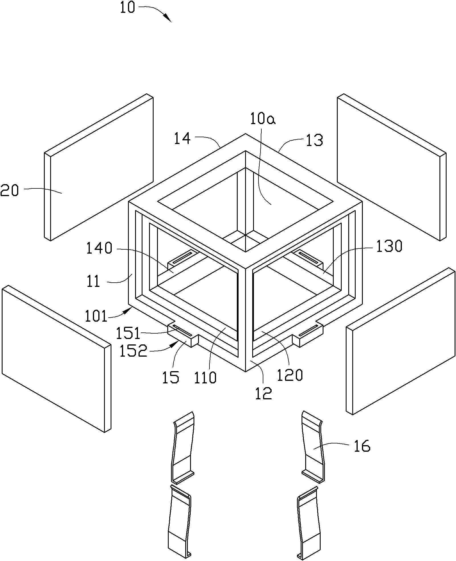
[0040] see figure 1 , The magnet fixing frame 10 provided by the first embodiment of the present invention is used to fix the magnet in the voice coil motor, which is roughly a square frame. It can be understood that the magnet holder 10 can also be in other shapes, such as a circle or other polygons.

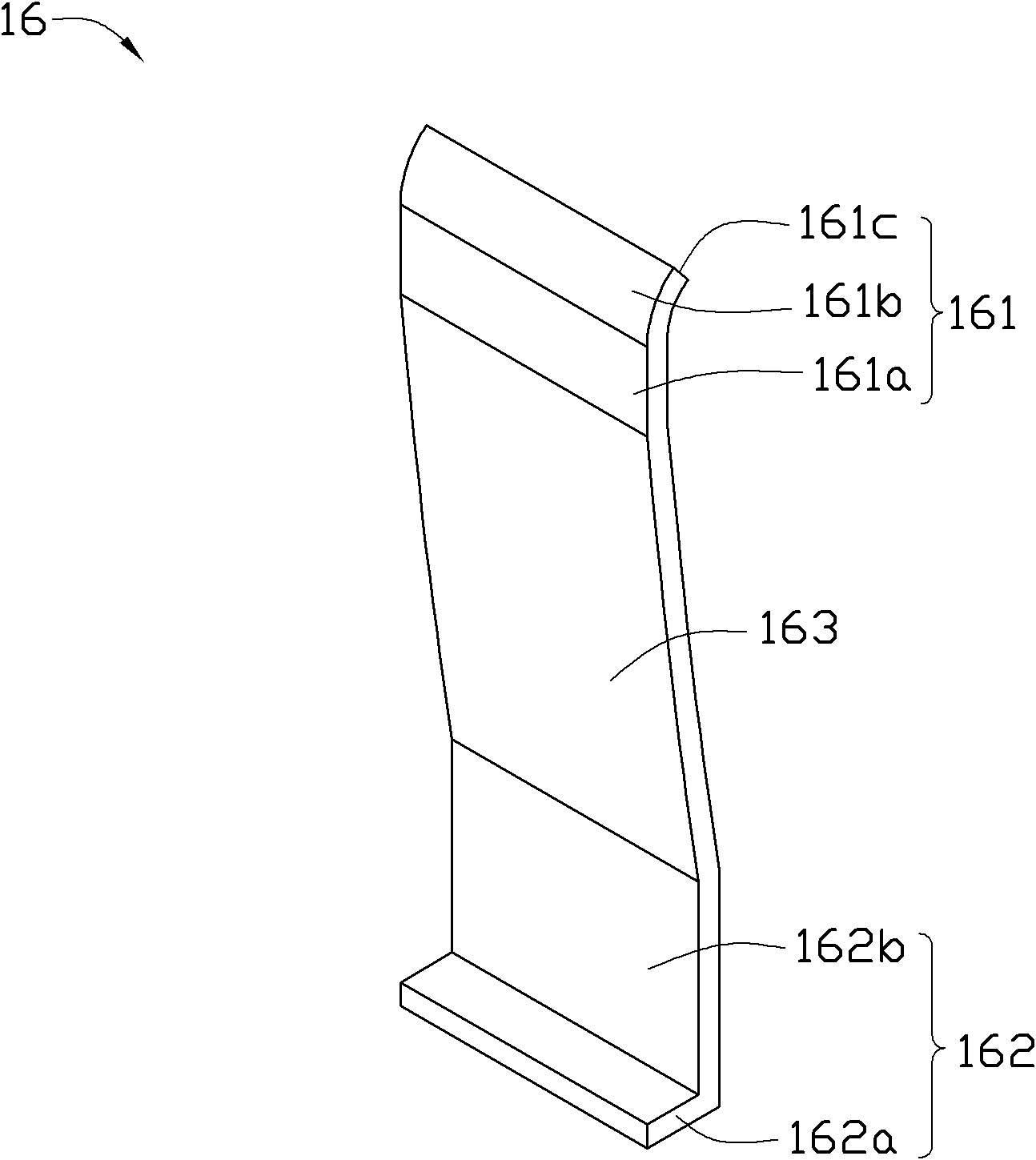
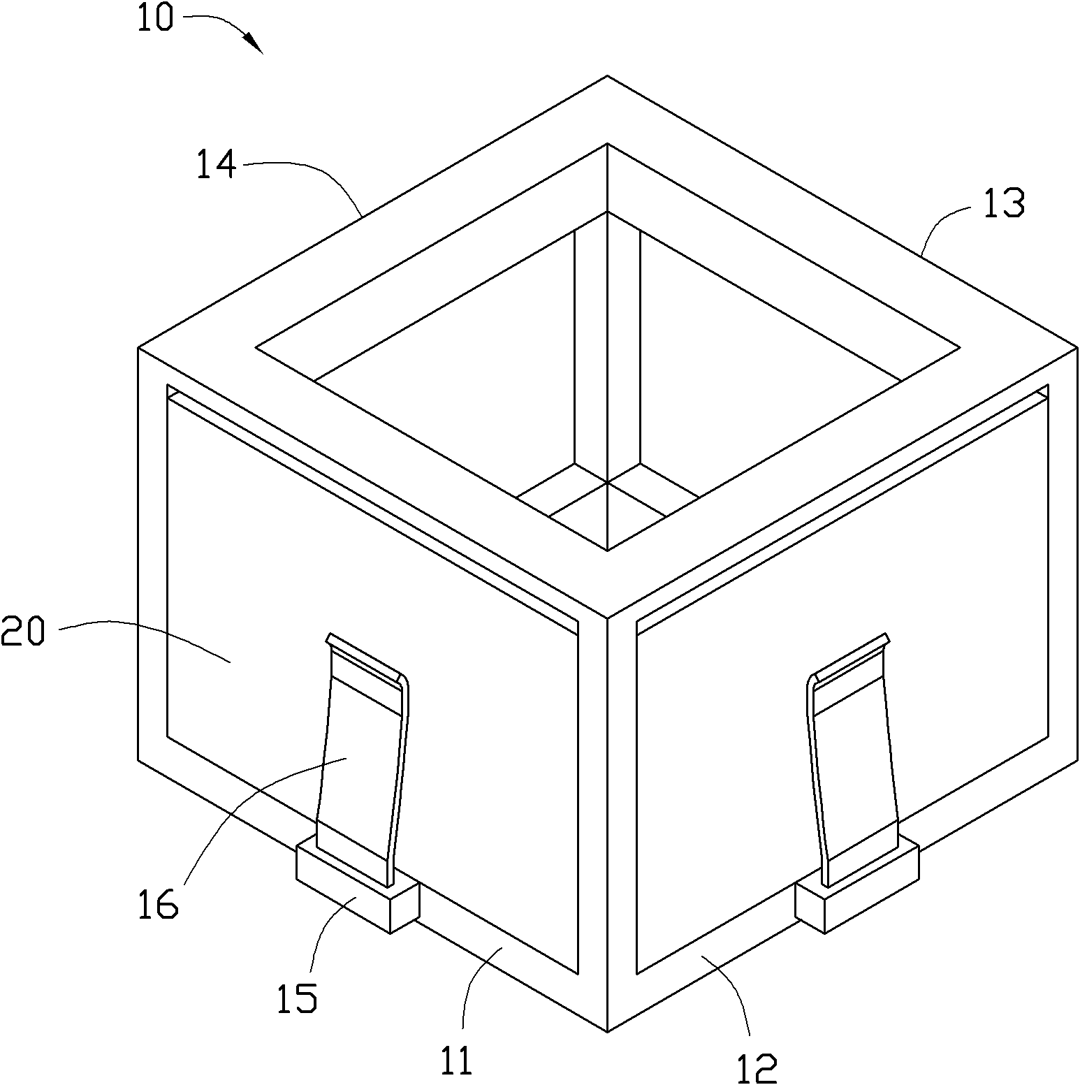
[0041] The magnet holder 10 includes a first side wall 11 , a second side wall 12 , a third side wall 13 , a fourth side wall 14 and four resisting elastic pieces 16 . The first side wall 11 , the second side wall 12 , the third side wall 13 , and the fourth side wall 14 connect end to end to form a receiving space 10 a. Wherein, the first side wall 11 is opposite to the third side wall 13 , and the second side wall 12 is opposite to the fourth side wall 14 .

[0042] The first sidewall 11 defines a first stepped hole 110 . The second sidewall 12 defines a second stepped hole 120 . The third sidewall 13 defines a third stepped hole 130 . The fourth sidewall 14 defines a fo...

no. 2 approach

[0051] see Figure 4 , is the voice coil motor 1 provided by the second embodiment of the present invention, the voice coil motor 1 includes a casing 30 and the magnet fixing frame 10 , and the magnet fixing frame 10 is fixed in the casing 30 .

[0052] The above-mentioned magnet fixing frame abuts and fixes the magnet through the resisting elastic piece, and only needs to install the resisting elastic piece during assembly, which can improve assembly efficiency and avoid product defects caused by glue dispensing.


PUM


Abstract

The invention relates to a magnet fixing frame, which is used for fixing a magnet in a voice coil motor. The magnet fixing frame comprises side walls and butting resilient sheets, wherein the side walls are provided with ladder holes for containing the magnet, and holding pieces are arranged at the periphery of the ladder holes. One end of each butting resilient sheet is buckled with the corresponding holding piece, and the other end of each butting resilient sheet is butted against the corresponding magnet to contain the magnet into the ladder holes. By fixing the magnet through the butting resilient sheets in a butting manner, the assembling efficiency can be improved by installing the butting resilient sheets in the assembling process, thereby avoiding rejects caused by dispensing adhesive. Furthermore, the invention relates to the voice coil motor using the magnet fixing frame.

Description

technical field [0001] The invention relates to a magnet fixing structure in a voice coil motor, in particular to a magnet fixing frame and a voice coil motor using the magnet fixing frame. Background technique [0002] The existing voice coil motor generally includes a fixing frame and a magnetic element. During assembly, the magnetic element is usually set at a preset position of the fixing frame, and then the magnetic element is bonded to the fixing frame by manual glue dispensing or an automatic needle dispensing system. Due to the polarity repulsion or attraction between the magnetic components, it is difficult to stably place the magnetic components at the preset position for dispensing during the dispensing process, especially when the dispensing volume is insufficient or the curing time is insufficient. , the magnetic element is easy to fall off, and the lens module is more likely to be polluted during the dispensing process. Therefore, fixing the magnetic element b...

Claims


Application Information

Patent Timeline
IPC IPC(8): H02K1/18H02K1/28
Inventor 黄建峰
Owner HONG FU JIN PRECISION IND (SHENZHEN) CO LTD
Why Eureka
Try Eureka