a curing device

A technology of curing device and curing zone, which is applied to devices, optics, instruments and other directions for coating liquid on the surface, can solve the problems of inability of ultraviolet curing device, and achieve the effect of avoiding a large number of bad products, reducing the action time and low cost.

Inactive Publication Date: 2015-09-16
BOE TECH GRP CO LTD +1
View PDF4 Cites 0 Cited by
  • Summary
  • Abstract
  • Description
  • Claims
  • Application Information

AI Technical Summary

Problems solved by technology

[0007] The technical problem to be solved by the present invention is to solve the problem that the existing ultraviolet light curing device cannot realize continuous assembly line production, the cost is high, and the curing efficiency is low, which causes the ultraviolet light curing delay of a large number of combined substrates, and the liquid crystal to seal the frame. Prolonged action time will lead to a large number of defects in the future, and the UV lamp consumes a lot of energy, and the energy is not used efficiently.

Method used


Image

  • a curing device
  • a curing device
  • a curing device

Examples


Embodiment Construction

[0027] Embodiments of the present invention will be further described in detail below in conjunction with the accompanying drawings and examples. The following examples are used to illustrate the present invention, but should not be used to limit the scope of the present invention.

[0028] In the description of the present invention, unless otherwise specified, "plurality" means two or more. The orientation or positional relationship indicated by the terms "upper", "lower", "left", "right", "inner", "outer", "front end", "rear end", "head", "tail" etc. is Based on the orientation or positional relationship shown in the drawings, it is only for the convenience of describing the present invention and simplifying the description, and does not indicate or imply that the referred device or element must have a specific orientation, be constructed and operated in a specific orientation, and therefore cannot be understood To limit the present invention.

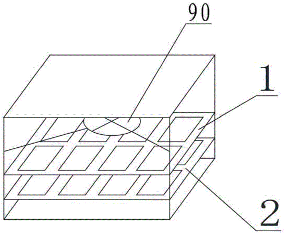
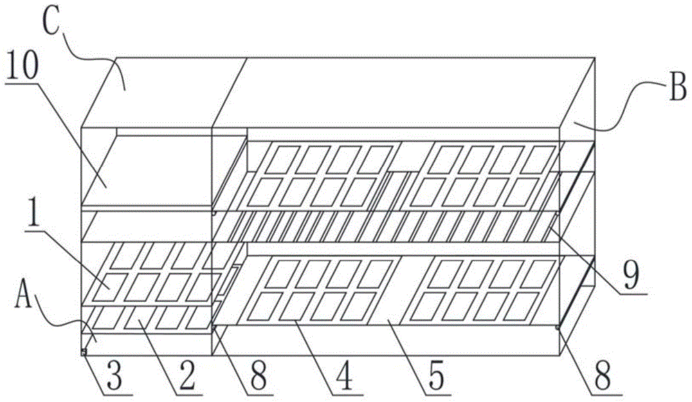
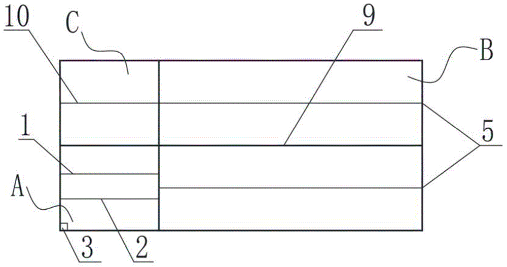
[0029] Such as figure 2 ...


PUM


Abstract

The invention relates to the technical field of liquid crystal display production equipment, in particular to a curing device and specific to a continuous curing device applicable to an ultraviolet curing stage. An apposition area of the curing device is used for making apposition plates, a curing area is internally provided with ultraviolet lamps used for curing the apposition plates, the ultraviolet lamps divide the curing area into an upper layer and a lower layer, the apposition area is communicated with the lower layer, an overturning area is communicated with the upper layer, and the apposition layer is communicate with the overturning area. The curing device is low in cost and high in curing efficiency, the curing area is divided into two parts through the ultraviolet lamps to enable the apposition area to perform ultraviolet curing along two sides of the ultraviolet lamps at the same time, a whole assembly line working process is formed through communication of the apposition area and the curing area, the ultraviolet curing stage of frame sealing adhesive has high continuity and high energy utilization rate, and delay time of the apposition plate in the curing stage is reduced greatly.

Description

technical field [0001] The invention relates to the technical field of liquid crystal display production equipment, in particular to a curing device, in particular to a continuous curing device suitable for the ultraviolet curing stage. Background technique [0002] Thin Film Transistor-Liquid Crystal Display (English name is Thin Film Transistor-Liquid Crystal Display, TFT-LCD for short) is a kind of liquid crystal display, which uses thin film transistor technology to improve image quality. TFT-LCDs are collectively referred to as LCDs, which are used in televisions, flat panel displays and projectors. Its production technology has been developed in recent decades, and its technology and process are becoming more and more mature. It has replaced cold cathode diode (English name is Cold Cathode Fluorescent Lamp, CCFL for short) display and has become the mainstream product in the display field. [0003] In the production process of the LCD panel, in order to make the liqui...

Claims


Application Information

Patent Timeline
Patent Type & Authority Patents(China)
IPC IPC(8): B05D3/06B05C13/02G02F1/1339
Inventor 周永山邵勇孟维欣
Owner BOE TECH GRP CO LTD
Why Eureka
Try Eureka