
Video playback method and apparatus

A video and video frame technology, applied in the field of video communication, can solve problems such as high network bandwidth requirements and difficult client access, and achieve the effect of reducing network bandwidth requirements

Active Publication Date: 2017-12-19
HANGZHOU HIKVISION DIGITAL TECH
View PDF2 Cites 8 Cited by
  • Summary
  • Abstract
  • Description
  • Claims
  • Application Information

AI Technical Summary

Problems solved by technology

[0010] In practical applications, not all networks can achieve 128Mbps bandwidth, especially the playback client and data forwarding server are often not in the same network segment. It is even more difficult to achieve
It can be seen that when using the above method for video playback, the requirements for network bandwidth are relatively high.

Method used


Image

  • Video playback method and apparatus
  • Video playback method and apparatus
  • Video playback method and apparatus

Examples


example 1

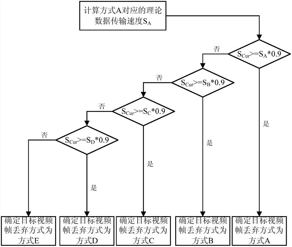
[0114] Example 1: Combining the information given in Table 1, figure 2 A schematic flow diagram of a target video frame selection method is provided, assuming that, in order of priority from high to low, the order of the five video frame discarding methods listed in Table 1 is: method A, method B, method C, In mode D and mode E, the first preset threshold is equal to 0.9.

[0115] Estimate the current data transfer speed S Cur After that, when determining the target video frame mode,

[0116] First, determine the video frame discarding method to be determined as method A, and calculate the theoretical data transmission speed S corresponding to method A according to the bandwidth compression rate of method A, the video playback magnification and the bit rate of the video to be played back A , to determine the current data transmission speed S Cur Whether it is greater than or equal to the theoretical data transmission speed S corresponding to mode A A *0.9, if yes, the dis...

example 2

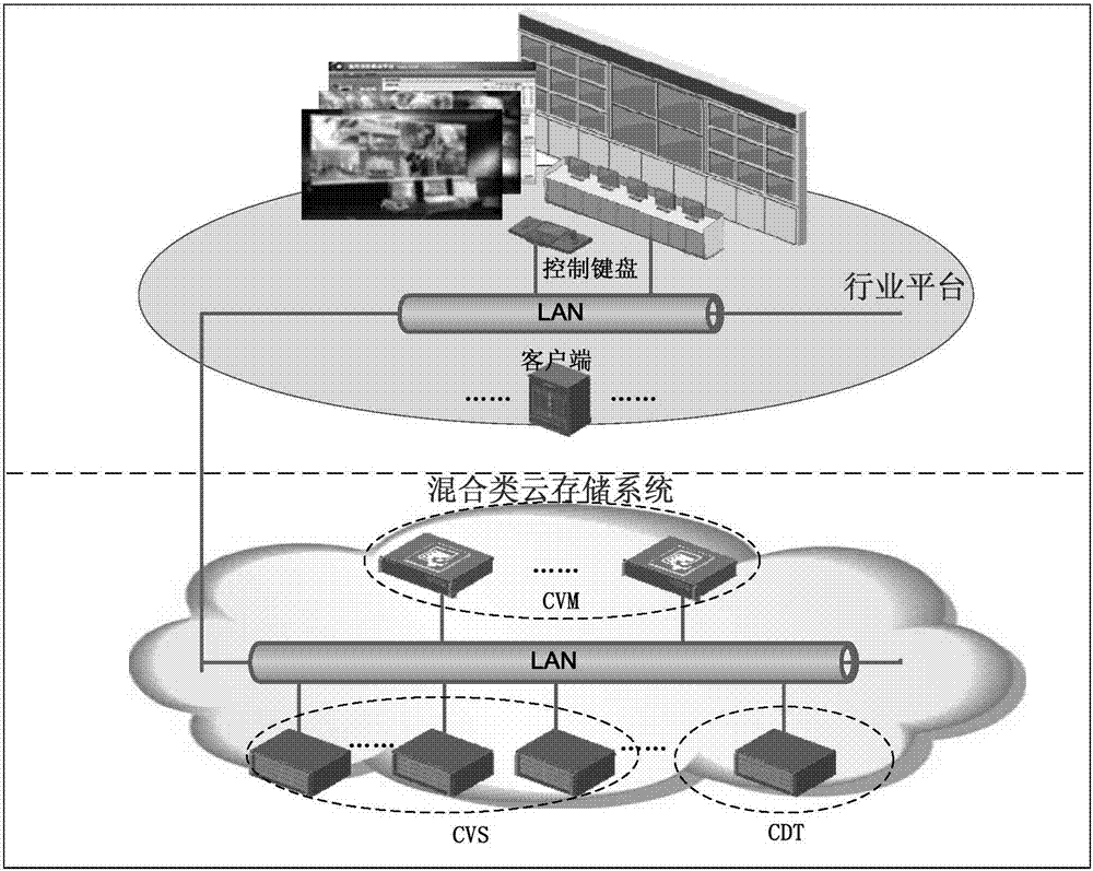
[0122] Example 2: Based on the video cloud storage system, the above video playback method is introduced.

[0123] image 3 The structural representation of the video cloud storage system that the embodiment of the present application provides, this video cloud storage system includes: client (video integrated platform), CVM (Cloud Video Master, storage management server), CVS (CloudVideo Slave, storage server) and CDT (Cloud Data Transmitter, data forwarding server).

[0124] Figure 4 for in image 3 Based on the above, a schematic diagram of a signaling flow of a video playback method is provided. Specifically, the video playback process includes the following steps:

[0125] Step1: The client sends a CDT address acquisition request to the CVM. After receiving the CDT address acquisition request, the CVM obtains the CDT address and returns an available CDT address to the client;

[0126] Step2: The client sends a video playback request to CDT according to the received C...


PUM


Abstract

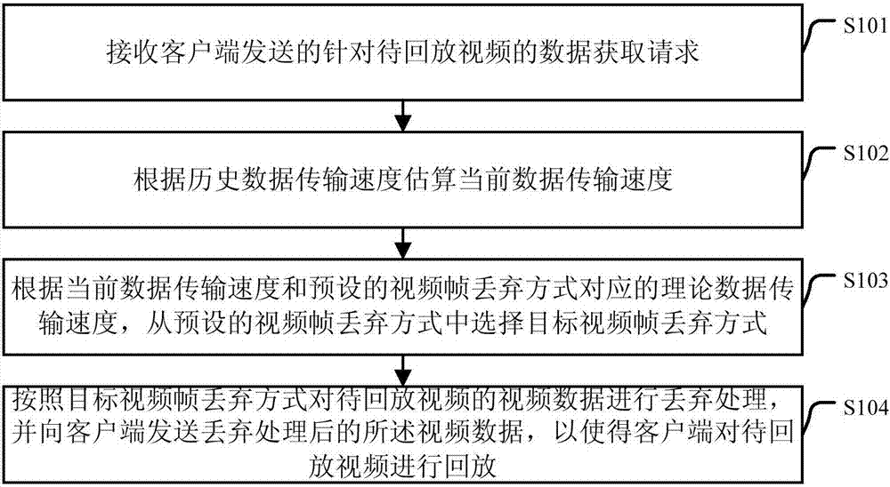
The embodiment of the invention discloses a video playback method and an apparatus, which relate to the technical field of video communication. The method comprises steps: a data acquisition request for a to-be-played-back video sent by a client is received, wherein a current data transmission speed is estimated on the basis of a history data transmission speed; a target video frame discarding mode is selected from the preset video frame discarding modes on the basis of the current data transmission speed and a theoretical data transmission speed corresponding to a preset video frame discarding mode, wherein the theoretical data transmission speed is determined on the basis of a video playback multiple speed; and a discarding processing is carried out on the video data of the to-be-played-back video in accordance with the target video frame discarding mode and the video data after the discarding processing are transmitted to the client, and thus, the client plays back the to-be-played-back video. When the scheme provided by the embodiment of the invention is applied, the requirement for network bandwidth during video playback can be reduced.

Description

technical field [0001] The present application relates to the technical field of video communication, in particular to a video playback method and device. Background technique [0002] With the rapid development of computer and network technology, video cloud storage system has been widely used, especially in the field of video surveillance. Common video cloud storage systems include: client, management server, storage server and data forwarding server. [0003] In addition, in the video cloud storage system, it is often necessary to play back the video at multiple speeds. In the prior art, video playback in the video cloud storage system generally includes the following steps: [0004] The client requests the storage management server for the address of the data forwarding server; [0005] The storage management server determines the data forwarding server, and sends the address of the data forwarding server to the client; [0006] The client sends a video playback reque...

Claims


Application Information

Patent Timeline
IPC IPC(8): H04N21/2343H04N21/2387H04N21/432H04N21/647
CPCH04N21/234363H04N21/2387H04N21/4325H04N21/64792H04N21/234381H04N21/23439H04N21/2393H04N21/2402H04N21/2662
Inventor 浦世亮张胜森丁光凯王伟林起芊汪渭春
Owner HANGZHOU HIKVISION DIGITAL TECH
Learn More