Shaft screening device

A technology for screening equipment and shaft diameters, applied in solid separation, classification, chemical instruments and methods, etc., can solve problems such as wrong screening and complicated rework procedures

Active Publication Date: 2017-12-22
宁波信基机械科技有限公司
View PDF6 Cites 7 Cited by
  • Summary
  • Abstract
  • Description
  • Claims
  • Application Information

AI Technical Summary

Problems solved by technology

At present, the existing problem is that the shaft parts taken out of the cleaning equipment are of different specifications. In order to facilitate classification and storage, it is often necessary to manually classify these shaft parts on the conveyor bel

Method used


Image

  • Shaft screening device

Examples


Embodiment Construction

[0013] The present invention will be described in further detail below by means of specific embodiments:

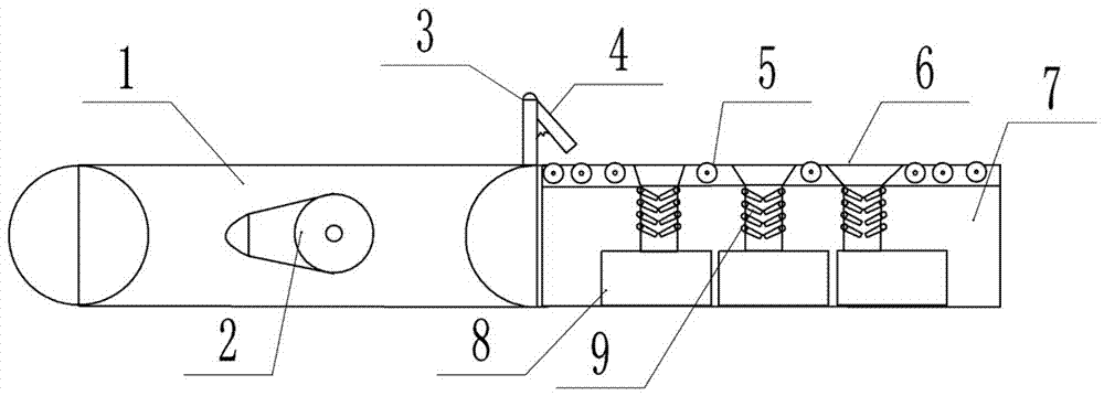
[0014] The reference signs in the drawings of the description include: conveyor belt 1, cam 2, discharge frame 3, baffle plate 4, drive roller 5, screening tank 6, base 7, material box 8, buffer plate 9.

[0015] The embodiment is basically as figure 1 Shown:

[0016] The shaft screening equipment of this embodiment includes a conveyor belt 1 for transporting shaft workpieces. A cam 2 is rotatably connected to the inside of the conveyor belt 1. The highest point of the movement of the cam 2 is higher than the upper surface of the conveyor belt 1. The output pipe of the conveyor belt 1 is fixedly connected. There is a discharge frame 3, a baffle 4 is hinged on the discharge frame 3, a spring connected to the side wall of the discharge frame 3 is provided on the baffle 4, and a screening mechanism is provided on one side of the conveyor belt 1, and the screening mechanism ...


PUM


Abstract

The invention belongs to the field of screening equipment, and particularly relates to a shaft screening device. The device comprises a conveying belt used for conveying shaft workpieces, a cam is rotatably connected into the conveying belt, an output pipe of the conveying belt is fixedly connected with a discharging frame, a baffle is hinged to the discharging frame, a spring connected with the side wall of the discharging frame is arranged on the baffle, the screening mechanism comprises a base, the top of the base and the upper surface of the conveying belt are equal in height, multiple transmission rollers are rotatably connected in the length direction of the upper surface of the base, and the distance of the gap between the transmission rollers is smaller than the diameter of a shaft, with the minimum shaft diameter, conveyed on the conveying belt, multiple screening grooves are formed in the base, diameters of the openings of the screening grooves are gradually increased in the length direction of the base, multiple sets of contact buffer plates are hinged to two sides of the inner wall of each screening groove, and a material box capable of sliding out of the base in a manner of being perpendicular to the length direction of the base is arranged at the bottom of each screening box. Manual operation is not needed, the shaft parts can be classified, and reworked re-checking is prevented.

Description

technical field [0001] The invention belongs to the field of screening equipment, and in particular relates to a shaft screening equipment. Background technique [0002] The shaft (shaft) is a cylindrical object that goes through the middle of the bearing or the middle of the wheel or the middle of the gear. A shaft is a mechanical part that supports and revolves with a rotating part to transmit motion, torque or bending moment. Manufacturers will produce many shaft parts with different diameters according to actual needs. After these shaft parts are produced and formed, they need to be polished or deburred on the surface, and then enter the cleaning equipment for cleaning. After cleaning, they are unified placed on the transport equipment and transported to the storage or boxing location. At present, the existing problem is that the shaft parts taken out of the cleaning equipment are of different specifications. In order to facilitate classification and storage, it is oft...

Claims


Application Information

Patent Timeline
IPC IPC(8): B07B13/07B07B13/16
CPCB07B13/07B07B13/16
Inventor 王健
Owner 宁波信基机械科技有限公司
Why Eureka
Try Eureka