Hose punching device and hose punching method

A punching device and hose technology, applied in metal processing and other directions, can solve the problems of difficulty in forming a single row of holes, inability to use hoses, and inability to adjust the size of the storage slot.

Pending Publication Date: 2017-12-22
LONGKOU MINING GRP
View PDF8 Cites 3 Cited by
  • Summary
  • Abstract
  • Description
  • Claims
  • Application Information

AI Technical Summary

Problems solved by technology

[0002] For the punching process of the hose, on the existing hose punching equipment (mainly a press) used in production, the punching die installed on the hose punching equipment performs a downward movement relative to the hose , to complete the punching of the hose; when punching the front side of the hose, if the mandrel is not used, it is easy to form two rows of holes corresponding to the upper and lower rows, and it is difficult to form a single row of holes, and the size of the storage slot is not adjustable, so it cannot be applied to For different types of hoses, the molds are not very versatile; if a mandrel is used, the mold structure is more complicated, and the washed waste is difficult to remove

Method used


Image

  • Hose punching device and hose punching method
  • Hose punching device and hose punching method
  • Hose punching device and hose punching method

Examples


Embodiment 1

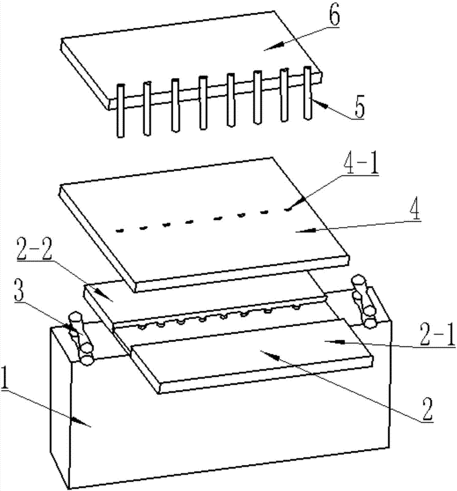
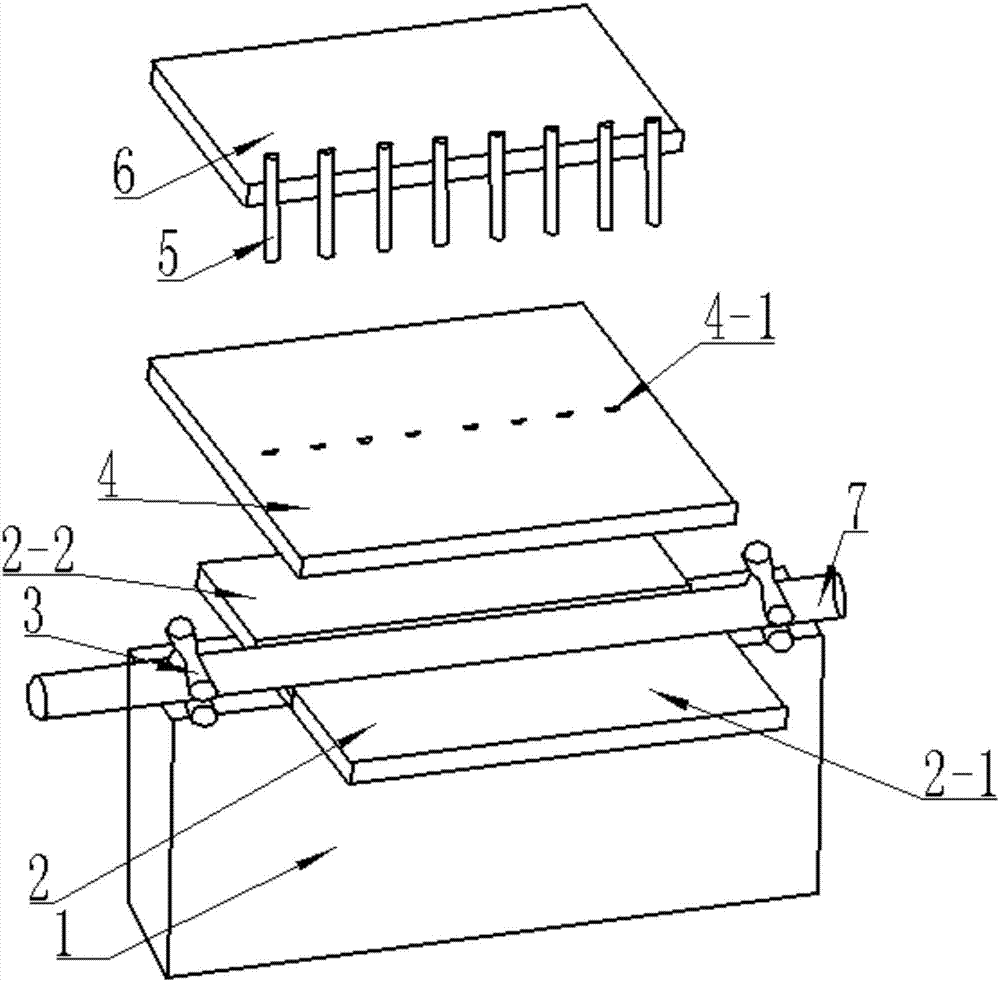
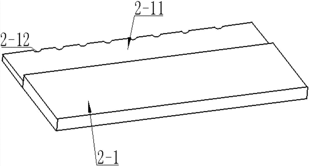
[0034] like Figure 1-Figure 4 As shown, a hose punching device includes a workbench 1, a placement plate 2, an extrusion plate 4, and a stamping plate 6, the placement plate is installed on the workbench 1, and the placement plate 2 is provided with There is a storage trough, one side of the storage trough is provided with a plurality of discharge holes 2-12, the extrusion plate 4 is arranged above the placement plate 2, and the extrusion plate 4 is provided with a plurality of The positioning hole 4-1 corresponding to the discharge hole 2-12, the stamping plate 6 is arranged above the extruding plate 4, and the stamping plate 6 is provided with a plurality of holes corresponding to the positioning hole 4-1. Corresponding to the punch 5, the discharge hole 2-12 and the positioning hole 4-1 are semicircular holes; the punch 5 includes an upper cylindrical punch 5-1 and a lower punch 5 -2, the section of the punch 5-2 is semicircular, such as Image 6 shown. The upper surfac...

Embodiment 2

[0041] The difference from Example 1 is that the lower end of the extruding plate 4 is provided with a protrusion (not shown in the figure) that is compatible with the storage slot, and the width of the storage slot is the same as that of the hose. 7 to match the diameter.

[0042] The working principle of the present invention is as follows:

[0043] When punching holes on the hose 7, firstly, the hose 7 is pulled by the tractor, so that the hose 7 passes through the guide wheel 3, and after entering the storage tank, the tractor stops working and triggers the extrusion plate cylinder to make the extrusion plate 4 downward Movement compresses the hose 7; then, triggers the punching plate cylinder, so that the punching plate 6 drives the punch 5 to move downward, punching the hose 7 to form a single row of round holes, after punching the holes, the extrusion plate 4 moves upward quickly; finally , repeat the preceding steps until the punching of the hose 7 is completed.

[0...


PUM


Abstract

The invention relates to a hose punching device which comprises a working table, a placement plate, a squeezing plate and a stamping plate. The placement plate is mounted on the working table; a placement groove is formed in the placement plate; the depth of the placement groove is smaller than the diameter of a hose and is slightly greater than twice of the wall thickness of the hose; a plurality of discharging holes are formed in one side of the placement groove; the squeezing plate is arranged above the placement plate; a plurality of positioning holes corresponding to the discharging holes are formed in the squeezing plate; the stamping plate is arranged above the squeezing plate; a plurality of punches corresponding to the positioning holes are arranged on the stamping plate; the discharging holes and the positioning holes are both semicircular holes; and a single row of holes can be processed in the hose. The invention further relates to a hose punching method. The hose punching device is utilized to flatten the hose first, and then the punches are utilized for punching to form the semicircular holes.

Description

technical field [0001] The invention relates to a hose punching device and a hose punching method. Background technique [0002] For the punching process of the hose, on the existing hose punching equipment (mainly a press) used in production, the punching die installed on the hose punching equipment performs a downward movement relative to the hose , to complete the punching of the hose; when punching the front side of the hose, if the mandrel is not used, it is easy to form two rows of holes corresponding to the upper and lower rows, and it is difficult to form a single row of holes, and the size of the storage slot is not adjustable, so it cannot be applied to For different types of hoses, the mold versatility is not high; if a mandrel is used, the structure of the mold is more complicated, and the washed waste is difficult to remove. Contents of the invention [0003] The present invention aims at the deficiencies in the above-mentioned prior art, and provides a hose ...

Claims


Application Information

Patent Timeline
Patent Type & Authority Applications(China)
IPC IPC(8): B26F1/02B26F1/14B26D7/01B26D7/08
CPCB26D7/01B26D7/08B26F1/02B26F1/14B26D2007/013
Inventor 王泮飞冯建波田昭君林强
Owner LONGKOU MINING GRP
Why Eureka
Try Eureka