A Feeder Coupled with Double Discharge Valve and Venturi Tube

A technology of Venturi tube and discharge valve, which is used in conveying bulk materials, transportation and packaging, conveyors, etc., can solve the problems of unstable material supply, blockage of Venturi structure, large fluctuation of material supply, etc., so as to facilitate material output. , The effect of small discharge impact and improved uniformity

Active Publication Date: 2019-07-19
CHINA COAL RES INST CCRI ENERGY SAVING TECH CO LTD +1
View PDF6 Cites 2 Cited by
  • Summary
  • Abstract
  • Description
  • Claims
  • Application Information

AI Technical Summary

Problems solved by technology

However, the current feeder of this structure mainly has the following five disadvantages: (1) the current unloading valve only plays the role of unloading, and the solid material is unevenly distributed inside the unloading valve, and the unloading valve itself The sealing effect is poor, which makes it difficult for solid materials to be uniformly unloaded into the Venturi structure, resulting in unstable subsequent material supply; (2) After the high-speed airflow is mixed with the solid materials, it is difficult to form a uniform gas-solid mixture, resulting in the output of the gas-solid mixture The quality is not uniform, resulting in large fluctuations in the supply; (3) the high-speed airflow and the solid material will collide with the pipe wall during the mixing process and the gas-solid mixture during the discharge process. In both cases, there must be energy loss, which shortens the supply. distance; (4) Due to the different transmission characteristics of different solid materials, the feeder has poor adjustability to different solid materials, and the feeding stability of the feeder cannot be controlled when transmitting solid materials with different characteristics; (5) Venturi There may be dead corners in the Venturi structure, and the material cannot be discharged in time, which not only easily causes blockage in the Venturi structure, but also affects the stability of the material supply.

Method used


Image

  • A Feeder Coupled with Double Discharge Valve and Venturi Tube
  • A Feeder Coupled with Double Discharge Valve and Venturi Tube
  • A Feeder Coupled with Double Discharge Valve and Venturi Tube

Examples


Embodiment 1

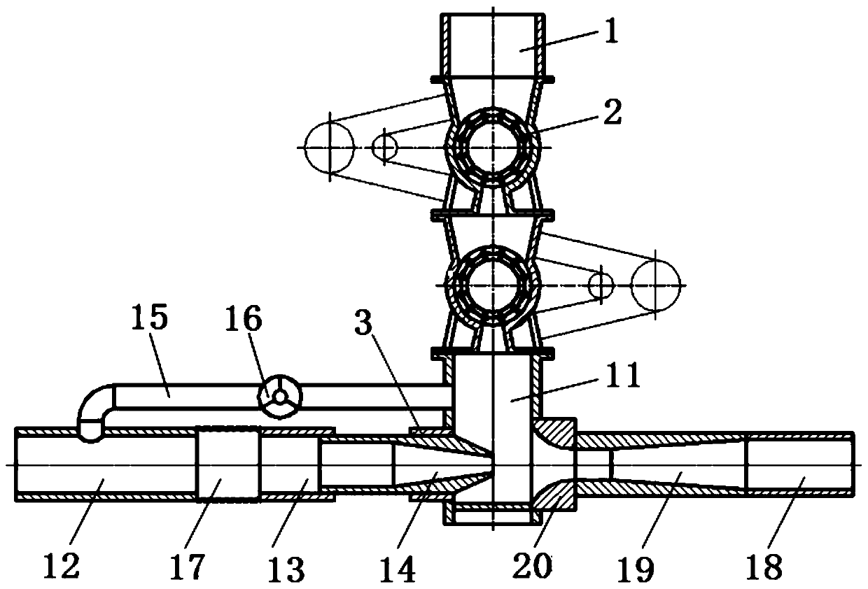
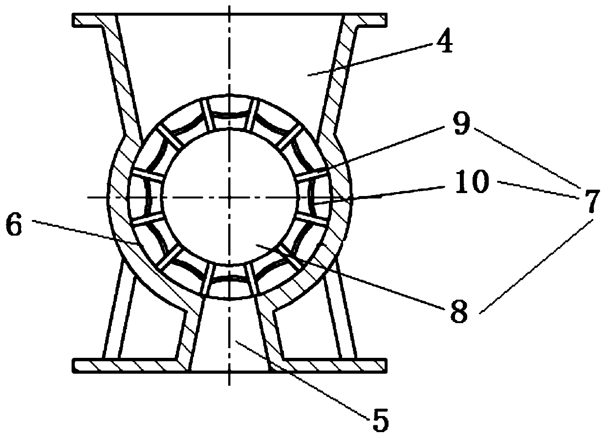
[0032] Such as figure 1 , figure 2As shown, the inner diameter of the rotating chamber 6 is 200mm, and there are 12 blades 9 evenly arranged in the circumferential direction on the discharge shaft 8, and the positions of the 12 base plates 10 on the impeller 7 are the same, so that the volumes of the 12 material cavities are the same, The sum of the volumes of the 12 chambers is 2.7L. The lower end of the material inlet 4 in the discharge valve 2 corresponds to 4 to 5 material cavities on the impeller 7, and the upper end of the material outlet 5 corresponds to 1 to 2 material cavities. The solid material enters the material chamber of the upper discharge valve 2 through the upper discharge pipe 1. When the speed of the discharge shaft 8 of the upper discharge valve 2 is 25r / min, since there are 12 material cavities in one circle of the impeller 7 , the discharge valve 2 at the upper end has 5 material cavities per second to participate in the discharge, and the material is...

Embodiment 2

[0034] Such as image 3 , Figure 4 As shown, the inner diameter of the rotating chamber 6 is 250mm, and there are 14 blades 9 evenly arranged in the circumferential direction on the discharge shaft 8, and the positions of the 14 base plates 10 on the impeller 7 are the same, so that the volumes of the 14 material cavities are the same, The sum of the volumes of the 14 chambers is 5.7L. The lower end of the feed port 4 in the discharge valve 2 corresponds to 3 to 4 material cavities on the impeller 7, and the upper end of the discharge port 5 corresponds to 1 to 2 material cavities. The solid material enters the material chamber of the upper discharge valve 2 through the upper discharge pipe 1. When the speed of the discharge shaft 8 of the upper discharge valve 2 is 25r / min, since there are 14 material cavities in one circle of the impeller 7 , the discharge valve 2 at the upper end has about 5.8 material cavities per second to participate in the discharge, and the material...

Embodiment 3

[0036] Such as Figure 5 , Figure 6 As shown, the inner diameter of the rotating chamber 6 is 300mm, and there are 16 blades 9 evenly arranged in the circumferential direction on the discharge shaft 8, and the positions of the 16 base plates 10 on the impeller 7 are the same, so that the volumes of the 16 material cavities are the same, The sum of the volumes of the 16 chambers is 8.8L. The lower end of the feed port 4 in the discharge valve 2 corresponds to 3 to 4 material cavities on the impeller 7, and the upper end of the discharge port 5 corresponds to 1 to 2 material cavities. The solid material enters the material chamber of the upper discharge valve 2 through the upper discharge pipe 1. When the speed of the discharge shaft 8 of the upper discharge valve 2 is 25r / min, since there are 16 material cavities in one circle of the impeller 7 , the discharge valve 2 at the upper end has about 6.7 material cavities per second to participate in the discharge, and the materia...


PUM


Abstract

The invention relates to a feeder with coupled double discharging valves and Venturi tubes. The feeder comprises a mixing room with an open top and a sealed bottom, two discharging valves stacked up and down are mounted on the top of the mixing room, upper and lower ends of the discharging valves are both provided with openings, wherein the upper opening end is a charging port in the shape of an inverted circular truncated cone, the lower opening end is a discharging port in the shape of a circular truncated cone, a rotary chamber is arranged between the charging port and the discharging port, an impeller is rotatably arranged in the rotary chamber, the impeller comprises a horizontally arranged discharging shaft rotatably connected to the rotary chamber, blades circumferentially and uniformly arranged on the discharging shaft, and bottom plates arranged between every two adjacent blades, a material cavity for filling materials is formed between each bottom plate and the corresponding two adjacent blades, the material cavities filled with materials are sealed with the side walls of the rotary chamber, the first Venturi tube and the second Venturi tube are tightly connected on the side wall of the mixing room, and the axes of the first Venturi tube and the second Venturi tube are collinear.

Description

technical field [0001] The invention relates to a feeder, in particular to a feeder with double discharge valves coupled with a Venturi tube. Background technique [0002] The feeder is widely used in the field of pneumatic transmission of solid materials. It is mainly composed of a discharge device and a material transmission device. The function of the discharge device is to uniformly discharge solid materials into the material transmission device. The high-speed air outputs the solid material quickly, uniformly and stably. At present, unloading valve and Venturi structure are commonly used unloading devices and material transmission devices, and the combination of unloading valve and Venturi structure is a commonly used feeder. The working principle of this type of feeder is: solid material from The top of the unloading valve enters, and the unloading valve unloads the solid material into the Venturi structure; the high-speed airflow rushes into the Venturi structure, fo...

Claims


Application Information

Patent Timeline
Patent Type & Authority Patents(China)
IPC IPC(8): B65G53/52B65G53/46
CPCB65G53/4625B65G53/52
Inventor 王乃继罗伟李殿新王乾张鑫梁兴刘力章王实朴于海鹏裘星刘振宇
Owner CHINA COAL RES INST CCRI ENERGY SAVING TECH CO LTD
Why Eureka
Try Eureka