Plate-and-frame filter press convenient for discharging

A technology of plate and frame filter press and unloading plate, which is applied in the direction of filtration and separation, separation methods, chemical instruments and methods, etc., and can solve problems such as unloading of easily damaged receiving equipment, reduction of unloading efficiency, and transfer of filter cakes. , to achieve a good cushioning effect, reduce the impact force, and improve the efficiency of collecting materials

Inactive Publication Date: 2020-01-03
苏子战
View PDF0 Cites 4 Cited by
  • Summary
  • Abstract
  • Description
  • Claims
  • Application Information

AI Technical Summary

Problems solved by technology

[0002] The plate and frame filter press is an equipment that realizes solid-liquid separation in industrial production. The filter cake after the filter press falls freely by gravity to realize unloading. During the unloading process, the filter cake falls to the receiving equipment, and the filter cake The impact force generated by directly falling onto the receiving equipment is relatively large, which is easy to damage the receiving equipme

Method used


Image

  • Plate-and-frame filter press convenient for discharging
  • Plate-and-frame filter press convenient for discharging
  • Plate-and-frame filter press convenient for discharging

Examples


Example Embodiment

[0019] Example 1

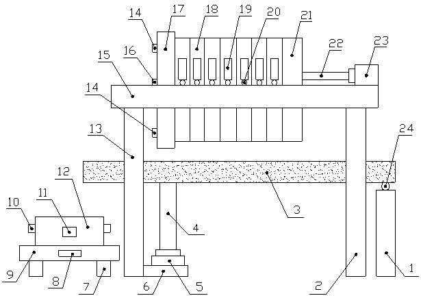
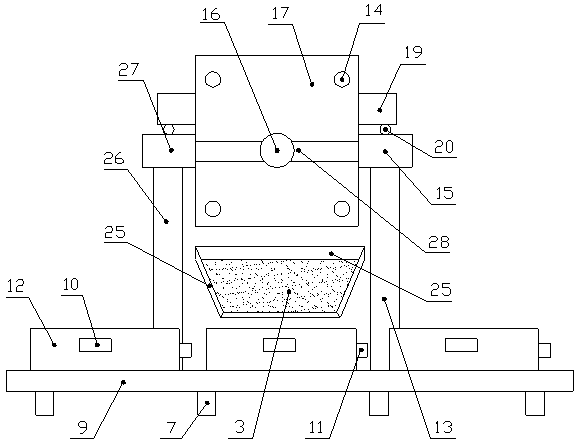
[0020] Such as Figure 1-4 As shown, a plate and frame filter press for easy unloading includes a support beam A15 and a support beam B27. The lower ends of the support beam A15 and the support beam B27 are respectively fixedly installed with a left leg A13 and a left support Leg B26, the right leg 2 is fixedly installed on the right side of the lower end of the supporting beam A13 and the supporting beam B26, and the connecting rod 28 and the thrust plate 17 are fixedly connected between the supporting beam A13 and the supporting beam B26, The upper ends of the support beam A15 and the support beam B27 are slidably connected with a filter plate 18, the filter plate 18 is located on the right side of the thrust plate 17, and the upper part of the front and rear ends of the filter plate 18 are fixedly connected with the connecting plate 19 A walking wheel 20 is installed at the lower end of the connecting plate 18, and the walking wheel 20 is slidably connected...

Example Embodiment

[0022] Example 2

[0023] Such as Figure 1-4 As shown, a plate and frame filter press for easy unloading includes a support beam A15 and a support beam B27. The lower ends of the support beam A15 and the support beam B27 are respectively fixedly installed with a left leg A13 and a left support Leg B26, the right leg 2 is fixedly installed on the right side of the lower end of the supporting beam A13 and the supporting beam B26, and the connecting rod 28 and the thrust plate 17 are fixedly connected between the supporting beam A13 and the supporting beam B26, The upper ends of the support beam A15 and the support beam B27 are slidably connected with a filter plate 18, the filter plate 18 is located on the right side of the thrust plate 17, and the upper part of the front and rear ends of the filter plate 18 are fixedly connected with the connecting plate 19 A walking wheel 20 is installed at the lower end of the connecting plate 18, and the walking wheel 20 is slidably connected...


PUM


Abstract

The invention discloses a plate-and-frame filter press convenient for discharging. The plate-and-frame filter press comprises a supporting beam A and a supporting beam B, a left supporting leg A and aleft supporting leg B are respectively mounted on the left sides of the lower ends of the supporting beam A and the supporting beam B; right supporting legs are mounted on the right sides of the lower ends of the supporting beam A and the supporting beam B; a connecting rod and a thrust plate are connected between the supporting beam A and the supporting beam B; the upper ends of the support beamA and the support beam B are slidably connected with a filter plate; a tightly pressing plate is arranged on the right side of the filter plate; the free end of a piston rod B of a hydraulic cylinderB mounted at the upper end of the connecting rod is connected with the right end of the tightly pressing plate; a discharging plate is arranged below the filter plate; the lower side of the right endof the left supporting leg A is connected with a supporting plate, the free end of a piston rod A of a hydraulic cylinder A arranged at the upper end of the supporting plate is hinged to the left side of the lower end of the discharging plate, the right side of the lower end of the discharging plate is connected with a supporting leg through a rotating shaft, and a conveying device is arranged below the left end of the discharging plate; a receiving box is arranged at the upper end of a conveying device. The plate-and-frame filter press has the advantages of being high in stability, small indischarging impact force and high in discharging efficiency.

Description

technical field [0001] The invention belongs to the technical field of filtering equipment, and in particular relates to a plate and frame filter press which is convenient for unloading. Background technique [0002] The plate and frame filter press is an equipment that realizes solid-liquid separation in industrial production. The filter cake after the filter press falls freely by gravity to realize unloading. During the unloading process, the filter cake falls to the receiving equipment, and the filter cake The impact force generated by directly falling onto the receiving equipment is relatively large, which is easy to damage the receiving equipment and affect the unloading, and the receiving equipment cannot transfer the filter cake out in time, reducing the unloading efficiency. Therefore, it is urgent to design a convenient operation , The unloading impact force is small, the buffer effect is good, the service life of the equipment is extended, the filter cake is transf...

Claims


Application Information

Patent Timeline
IPC IPC(8): B01D25/21B01D25/34
CPCB01D25/21B01D25/34
Inventor 苏子战史晓勇
Owner 苏子战
Why Eureka
Try Eureka