Projection lens system

A technology of projection lens and lens, which is applied in the field of camera lens, can solve the problems of enlarged image points, affecting the accuracy of three-dimensional object outline restoration, and the reduction of the definition of restored three-dimensional objects, so as to achieve the effect of maintaining a stable focal length

Active Publication Date: 2017-12-22
JIANGXI LIANCHUANG ELECTRONICS CO LTD
View PDF14 Cites 31 Cited by
  • Summary
  • Abstract
  • Description
  • Claims
  • Application Information

AI Technical Summary

Problems solved by technology

[0004] In the existing projection lens system products, there is a problem that the focal length f of the lens changes greatly with the change of the use environment temperature, which will lead to a significant change in the angle of the projected light from the lens, changing the original light information, and thus This leads to errors in the calculation of the entire system, which affects the accuracy of the contour restoration of 3D objects; there is also the problem that with the change of ambient temperature, the projected image points become larger, which will also lead to a decrease in the definition of 3D objects restored by the system

Method used


Image

  • Projection lens system
  • Projection lens system
  • Projection lens system

Examples


Embodiment 1

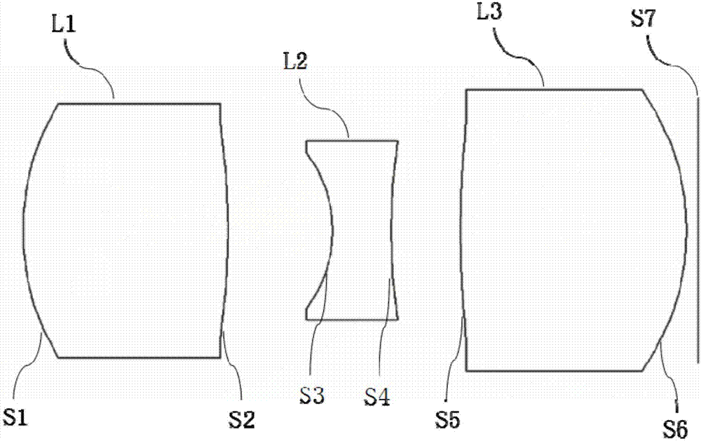
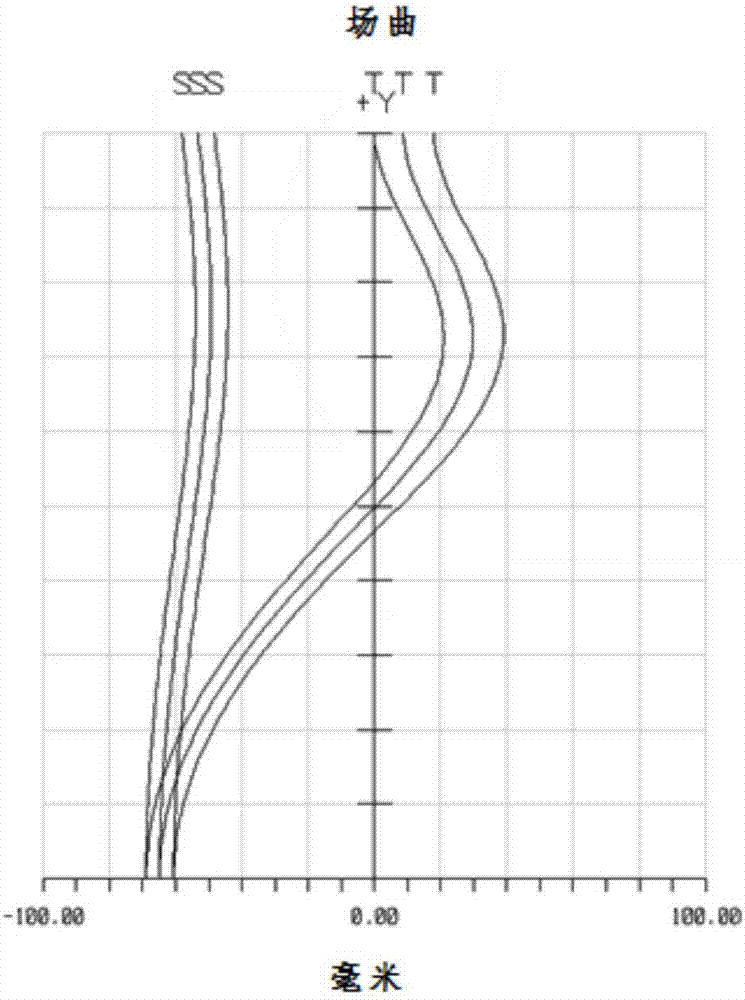
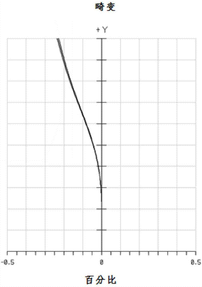
[0104] The structural diagram of the projection lens system of this embodiment can refer to figure 1 , see also Figure 2a , 2b and Figure 3, the relevant parameters of each lens in the projection lens system are shown in Table 1-1.

[0105] Table 1-1

[0106]

[0107] The parameters of each lens aspheric surface in this embodiment are shown in Table 1-2.

[0108] Table 1-2

[0109]

Embodiment 2

[0111] see Figure 4 , Figure 5a , 5b and Figure 6 , is the projection lens system provided in the second embodiment of the invention, and the relevant parameters of each lens in the projection lens system are shown in Table 2-1.

[0112] table 2-1

[0113]

[0114]

[0115] The parameters of each lens aspheric surface in this embodiment are shown in Table 2-2.

[0116] Table 2-2

[0117]

Embodiment 3

[0119] see Figure 7 , Figure 8a , 8b and Figure 9 , is the projection lens system provided in the third embodiment of the invention, and the relevant parameters of each lens in the projection lens system are shown in Table 3-1.

[0120] Table 3-1

[0121]

[0122] The parameters of each lens aspheric surface in this embodiment are shown in Table 3-2.

[0123] Table 3-2

[0124]

[0125]


PUM


Abstract

The invention discloses a projection lens system. The projection lens system sequentially comprises a first lens with positive focal power, a second lens with negative focal power, a third lens with positive focal power and a diaphragm from an object side to an image side along an optical axis, and is characterized in that an object-side surface of the first lens is a convex surface; an image-side surface of the third lens is a convex surface; and the optical centers of the lenses are located at the same straight line. The projection lens system satisfies the following conditions: f12>f3, (dn/dt)1<-50*10<-6>/DEG C, (dn/dt)2<-50*10<-6>/DEG C, and (dn/dt)3>-10*10<-6>/DEG C, wherein f12 represents the combined focal length of the first lens and the second lens, f3 represents the focal length of the third lens, and (dn/dt)1, (dn/dt)2 and (dn/dt)3 respectively represent changes rates of refractive indexes of the first lens, the second lens and the third lens along with the temperature. The projection lens system can cancel out influences imposed on the focal length by thermal expansion brought about by the lenses and structural members due to reasonable distribution of the change rate of the refractive index of each lens along with the temperature, thereby being capable of realizing stable focal length and being applicable to different temperature occasions.

Description

technical field [0001] The invention relates to the field of camera lens technology, in particular to a projection lens system. Background technique [0002] With the rapid development of smart phones, innovative technologies are constantly emerging in the camera functions of mobile phones, such as the 3D imaging technology promoted by Apple, which is an optical sensing technology based on 3D structured light, which can be used for face and gesture recognition, enhanced The camera function brings new AR applications, transforming optical images from the past two-dimensional space to three-dimensional space, thus bringing a more real and clear perception experience. [0003] 3D structured light means that after specific laser information is projected onto the surface of an object, it is collected by a camera, and information such as the position and depth of the object is calculated according to the change of light information caused by the object, and then the entire three-d...

Claims


Application Information

Patent Timeline
Patent Type & Authority Applications(China)
IPC IPC(8): G02B13/00G02B13/18G02B1/00G02B1/04G02B7/02
CPCG02B7/021G02B13/00G02B13/18G02B1/00G02B1/041G02B9/16G02B27/0025G01B11/2513G01B5/0014G02B5/005
Inventor 刘绪明王克民曾吉勇王立忠曾昊杰鲍宇旻陈伟建
Owner JIANGXI LIANCHUANG ELECTRONICS CO LTD
Why Eureka
Try Eureka