
Microscope for physics teaching

A microscope and physics technology, applied in the field of microscopes and microscopes for physics teaching, to achieve the effect of facilitating distance learning

Pending Publication Date: 2017-12-22
佛山卓博斯社机械科技有限公司
View PDF9 Cites 2 Cited by
  • Summary
  • Abstract
  • Description
  • Claims
  • Application Information

AI Technical Summary

Problems solved by technology

[0004] In view of the deficiencies in the prior art, the purpose of the present invention is to provide a microscope for physics teaching, to solve the problem that the existing microscope for physics teaching cannot directly present the image on the display, so that students can observe the image more intuitively. And remote data transmission of observed images or videos

Method used


Image

  • Microscope for physics teaching
  • Microscope for physics teaching
  • Microscope for physics teaching

Examples


Embodiment Construction

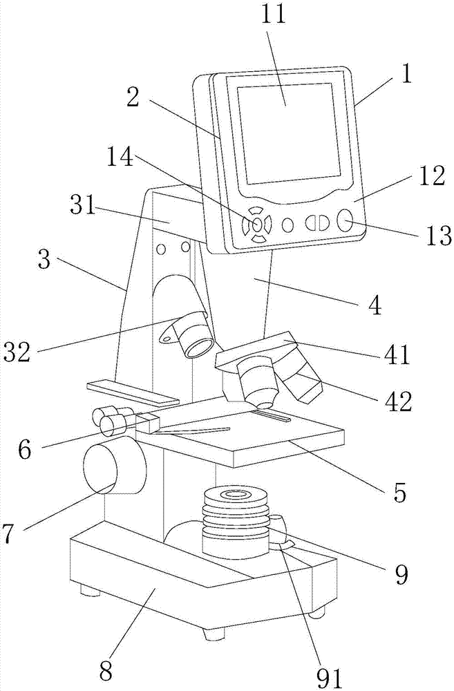
[0018] In order to make the technical means, creative features, goals and effects achieved by the present invention easy to understand, the present invention will be further described below in conjunction with specific embodiments.

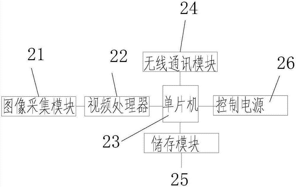
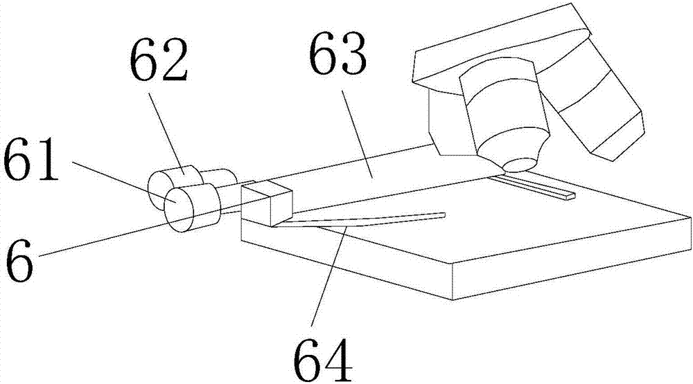
[0019] see Figure 1 to Figure 3 , the present invention provides a microscope technical solution for physics teaching: its structure includes a controller 1, a video remote control system 2, a mirror frame 3, a lens barrel 4, a stage 5, a stage positioner 6, a focusing hand Wheel 7, microscope base 8, condenser lens 9, described mirror frame 3 top is provided with controller 1, and described mirror frame 3 is provided with telescopic bracket 31, and described telescopic bracket 31 is flexibly connected with mirror frame 3, so The telescopic bracket 31 is perpendicular to the controller 1, the bottom of the telescopic bracket 31 is welded to the lens barrel 4, the lens barrel 4 is provided with a lens turntable 41 and an objective lens 42, and the...


PUM


Abstract

The present invention discloses a microscope for physics teaching. The structure of the microscope comprises a controller, a video remote control system, a microscope rack, a microscope barrel, an objective table, an objective table locator, a focusing handwheel, a microscope pedestal and a condenser lens. The top end of the microscope rack is provided with a controller, the microscope rack is provided with a telescoping support, the telescoping support is movably connected with the microscope rack, the telescoping support is perpendicular to the controller, the bottom portion of the telescoping support is welded with the microscope barrel, the microscope barrel is provided with a lens rotation table and an objective lens, the lens rotation table is in excessive matching with the microscope barrel, the objective lens is in threaded connection with the lens rotation table, the objective table is arranged at the lower portion of the microscope barrel, the objective table is perpendicular to the microscope rack, the objective table is provided with the objective table locator, and the side end of the microscope rack is provided with the focusing handwheel. A display screen and a video remote control system are employed to directly present images on the display screen to allow students to more visually observe images and perform remote data transmission of the observed images or video so as to facilitate remote learning.

Description

technical field [0001] The invention is a microscope for physics teaching, which belongs to the technical field of microscopes for physics teaching. Background technique [0002] A microscope is an optical instrument composed of a lens or a combination of several lenses, and it is a sign that human beings have entered the atomic age. It is mainly used to magnify tiny objects into instruments that can be seen by human eyes. Microscopes are divided into optical microscopes and electron microscopes: Optical microscopes were first invented by Jansen and his sons in the Netherlands in 1590. [0003] The existing open technology application number is: a microscope of 201220734337.1, including a microscope, the microscope is provided with a mirror base, and the microscope includes an eyepiece, a lens barrel, an adjusting focus screw, an objective lens, a tablet clip, a stage and a mirror, and the Both sides of the reflector are provided with a reflector rotating frame and auxil...

Claims


Application Information

Patent Timeline
Patent Type & Authority Applications(China)
IPC IPC(8): G02B21/36G02B21/32
CPCG02B21/32G02B21/365G02B21/368
Inventor 张宗伟
Owner 佛山卓博斯社机械科技有限公司
Learn More