
Observing tool and observing method using the same

a technology of observing tool and observing method, which is applied in the field of observation technique of transparent microobjects, can solve the problems of hugely expensive parts of modulation elements and inconvenient use, and achieve the effect of enhancing contras

Inactive Publication Date: 2007-08-02
ECI INC
View PDF6 Cites 13 Cited by
  • Summary
  • Abstract
  • Description
  • Claims
  • Application Information

AI Technical Summary

Benefits of technology

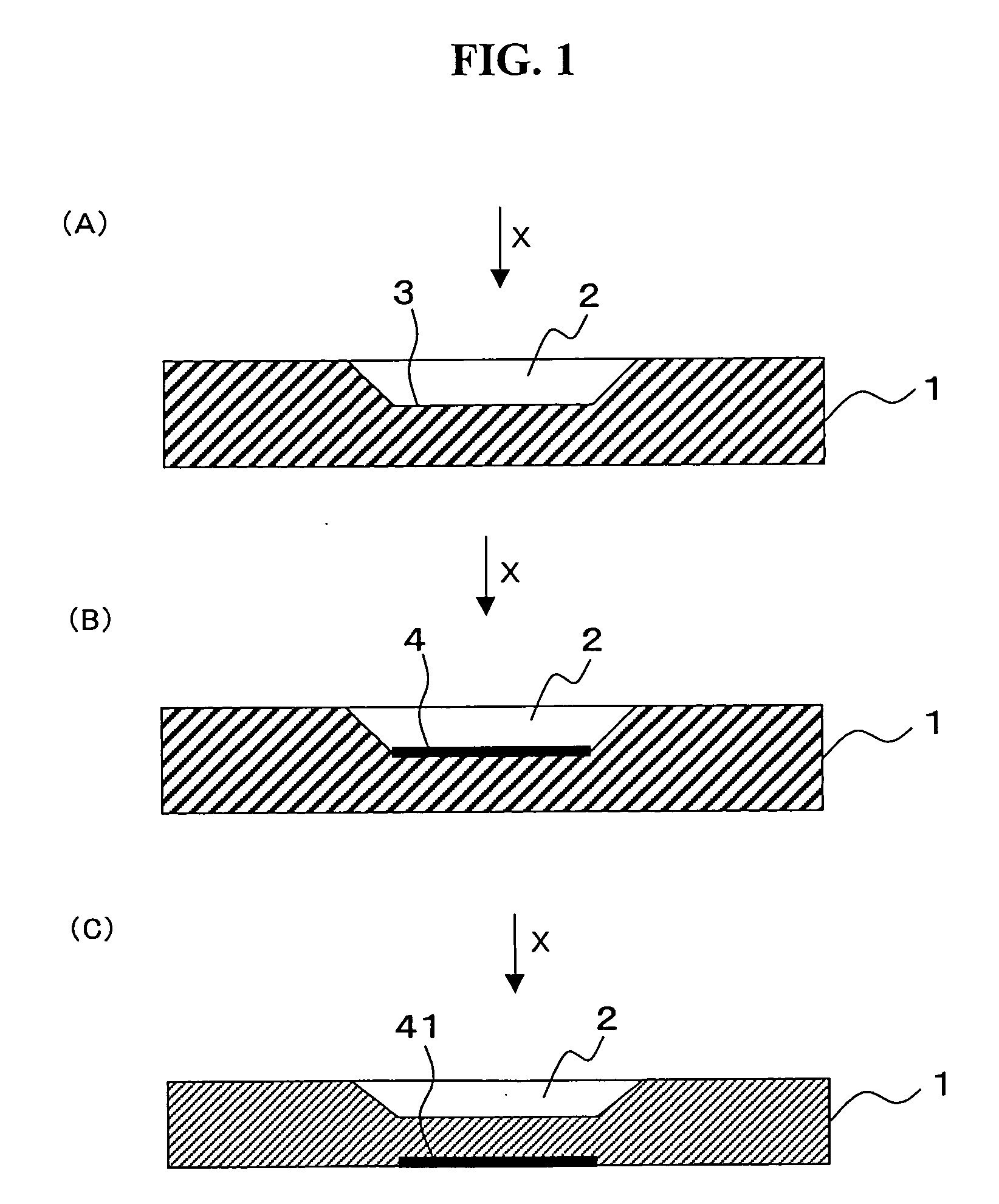
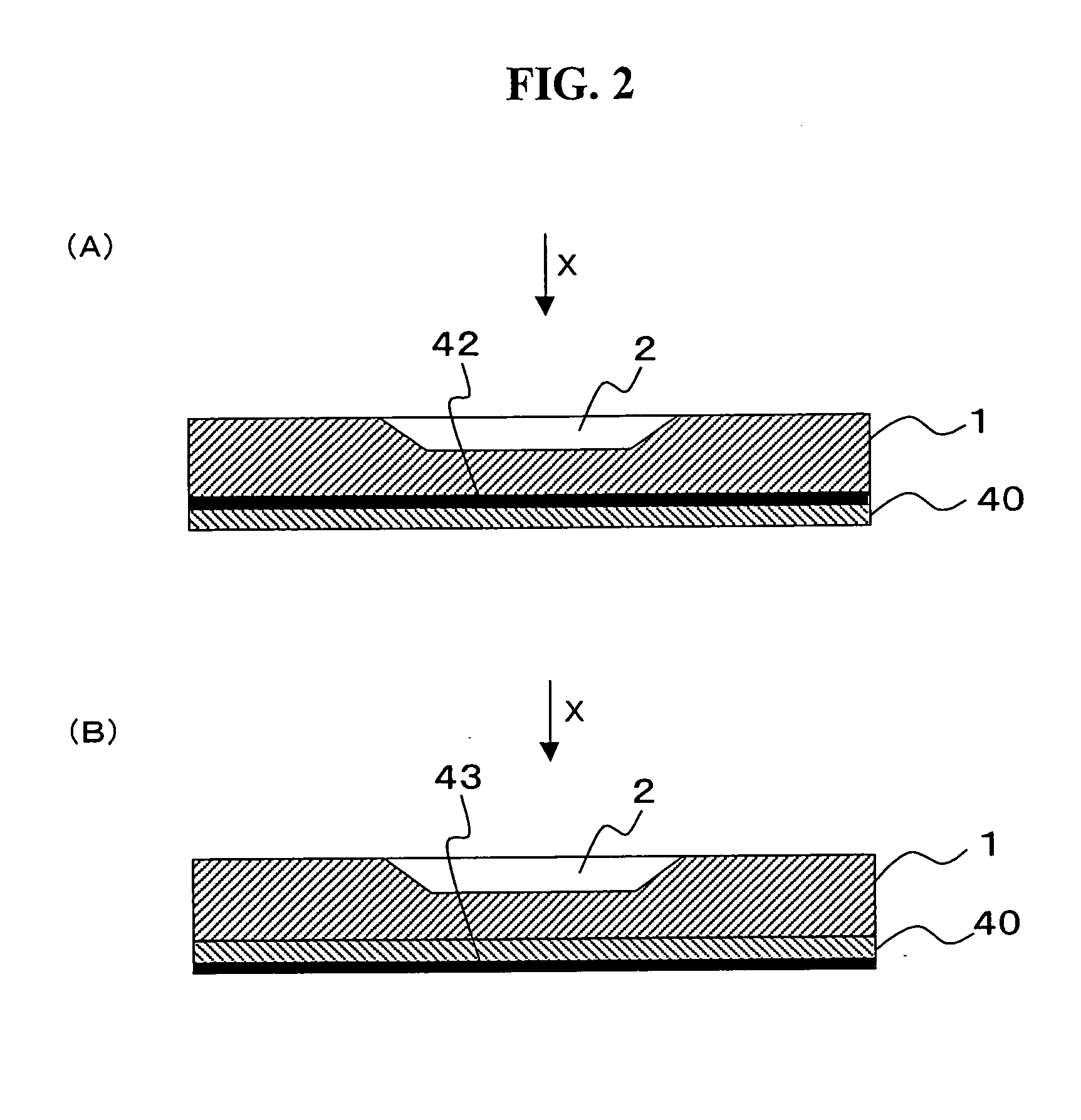
"The present invention provides a technique for observing transparent micro-objects without using expensive and inconvenient special modulation elements required for special observing methods. The technique involves using an observing tool with a reflection plane to reflect vertical lighting via an optical system having an objective lens. The tool stores the observation target, which can be a micro-object such as a cell, and the distance between the target and the reflection plane is optimized for observation. The technique allows for simple observation without the need for a special device."

Problems solved by technology

These particular modulation elements are hugely expensive, and in many cases, they are also inconvenient in usage, such that the modulation elements should be switched, for example, every time when a magnification of the objective lens 706 is changed.

Method used


Image

  • Observing tool and observing method using the same
  • Observing tool and observing method using the same
  • Observing tool and observing method using the same

Examples


example

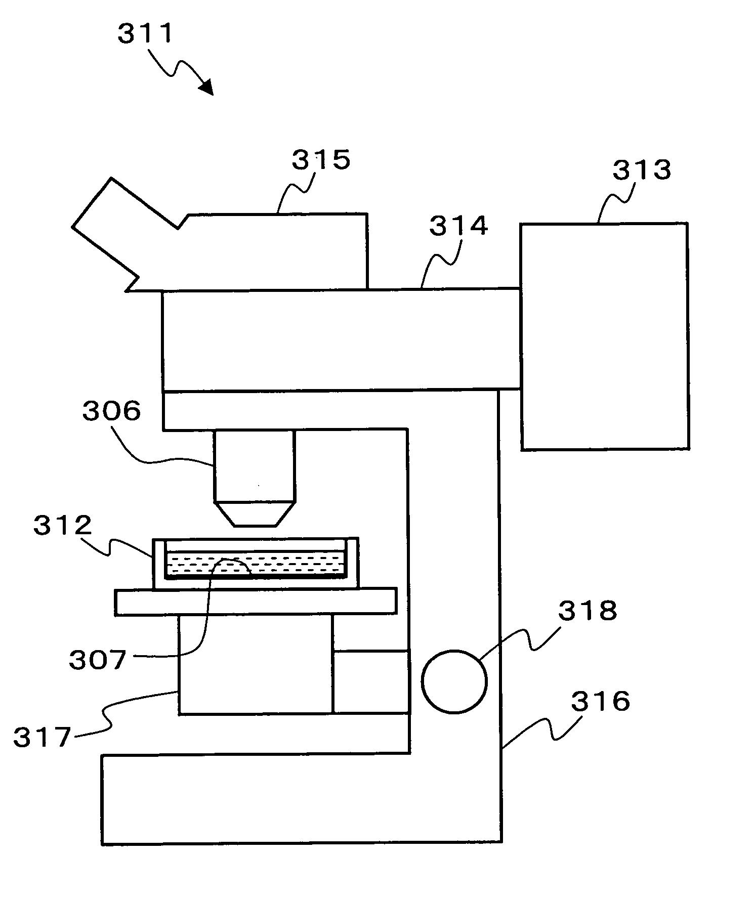
[0102]FIG. 18 is a photograph showing the case where a cell is observed and photographed from the lower side, using the observing tool as shown in FIG. 3(A2). Structure 1 is made of silicon wafer, and an observing tool having a distance a being 5 μm between the cover glass 5 and the reflection plane, is used. Condition for photographing is as the following;

Photographic apparatus: CCD digital video camera CL-211H (Watec America Co., Las Vegas, Nev.)

Lighting system: EPI-U (Nikon, Kawasaki, Japan)

Objective lens: ×20

Culture solution: RPMI 1640 buffer solution added with 20 mM HEPES and 0.1% bovine serum albumin was used.

Cell: Acidophilic leucocyte

[0103] Acidophilic leucocyte refined by a negative selection by the magnetism beads coupled with anti-CD 16 immune body against granulocyte fractionation in human being blood, was used. As for the magnetic beads, Dynal magnetic particle concentrator (Dynal A. S., Oslo, Norway) was used, and an operation was conducted according to a u...


PUM


Abstract

A transparent small object such as a cell can be simply observed without using any special modulating element needed for special observing methods. An observing tool for containing an object to be observed is used for a method for observing the object by illuminating the object with vertical illuminating light through an optical system having an objective lens. The observing tool has a reflective surface that reflects vertical illumination light when the object is observed. The reflective surface is provided on the front surface of the observing tool facing to the objective lens or on the back opposed to the front surface. The observing tool has a container holding a liquid. Using the observing tool, a cell or the like can be observed along with the culture solution.

Description

TECHNICAL FIELD [0001] The present invention relates to an observation technique of a material body, and in particular, it relates to an observation technique of a transparent micro-object such as a cell. BACKGROUND [0002] Conventionally, a transmission observation microscope has been used for observing a micro transparent object such as a cell. In order to observe an internal structure or a form of living unstained cell with high contrast, it has been necessary to use a microscope provided with a particular kind of lens, together with a particular kind of condenser having a phase contrast ring and / or a differential interference prism, such as a phase-contrast microscope, relief phase contrast microscope, differential interference microscope, and polarization microscope. [0003] Specifically, a special observing method is widely employed, for example, represented by a phase contrast method, focal illumination method, and differential interference method, as a method which observes by...

Claims


Application Information

Patent Timeline
Patent Type & Authority Applications(United States)
IPC IPC(8): G02B21/00
CPCG02B21/34
Inventor KANEGASAKI, SHIROHAYASHI, SHINICHI
Owner ECI INC
Learn More