
Optical system for occupancy sensing, and corresponding method

a technology of occupancy sensing and optical system, applied in optical detection, instruments, electrical equipment, etc., can solve the problems of inability to produce a 2d or 3d view on the occupancy of a space by people and objects, relatively high power consumption of cameras, and inability to generate numerical or statistical information for occupancy systems, etc., to achieve accurate determination of background/foreground pixels and accurate determination of 2d/3d occupancy

Active Publication Date: 2013-03-21
SENSO2ME
View PDF22 Cites 11 Cited by
  • Summary
  • Abstract
  • Description
  • Claims
  • Application Information

AI Technical Summary

Benefits of technology

The current invention proposes a system that uses multiple optical line sensors with a light-integrating device to integrate all light rays with certain geometric constraints. This approach makes it beneficial for applications such as 2D occupancy sensing and pick-and-place machine vision. By integrating along a single direction, the required number of sensing elements is reduced, simplifying the observation and post-processing. The line sensors are particularly useful because of their low power consumption, high data rates, and privacy-friendly nature. Additionally, the line sensors can be battery-operated, without needing changes in infrastructure or wiring. The system can also track changes between successive scan lines to accurately determine background / foreground pixels and 2D / 3D occupancy maps.

Problems solved by technology

Such one dimensional occupancy systems can generate numerical or statistical information but are not able to produce a 2D or 3D view on the occupancy of a space by people and objects.
The cameras have a relatively high power consumption as a result of which it is difficult to operate them on battery power for the purpose of occupancy sensing.
Regular cameras produce detailed, high resolution images which further may pose these systems at risk of privacy breach when used for occupancy sensing.
At last, the images generated by real-time still or video cameras require high bit rates and expensive image processing in order to turn the images into a 2D occupancy map.
A single top-view camera reduces the costs and processing requirements in comparison with multiple cameras, but still suffers from excessive power consumption, the need for wiring, and the risk for privacy breaches.
Moreover, a single top-view camera may loose accuracy when used in large rooms or rooms with a more complex geometry.
Existing solutions based on pressure sensors integrated in carpets, seats, flooring, etc. have as main disadvantage their intrusive nature in the interior of the room.
Occupancy sensing systems based thereon require expensive alterations to existing infrastructure in case of renovation, or limit the choice of flooring materials significantly in case of new construction.
In addition, these pressure sensor based occupancy sensing systems involve wiring for power and data because their power consumption does not allow battery-based operation.
State of the art occupancy sensing systems based on active sensors such as radar, ultrasound or radiofrequency (RF) based beacons typically need extensive noise cancellation and excessive processing because direction of arrival methods have to be applied.
The position measurements obtained with these technologies are not as accurate as can be achieved with camera-based systems.
Their power consumption is relatively high—they are active sensors—whereas their angular resolution is rather limited.
Their angular resolution is limited and as a result of the binary output, also the accuracy obtainable with PIR technology is limited.

Method used


Image

  • Optical system for occupancy sensing, and corresponding method
  • Optical system for occupancy sensing, and corresponding method
  • Optical system for occupancy sensing, and corresponding method

Examples


Embodiment Construction

)

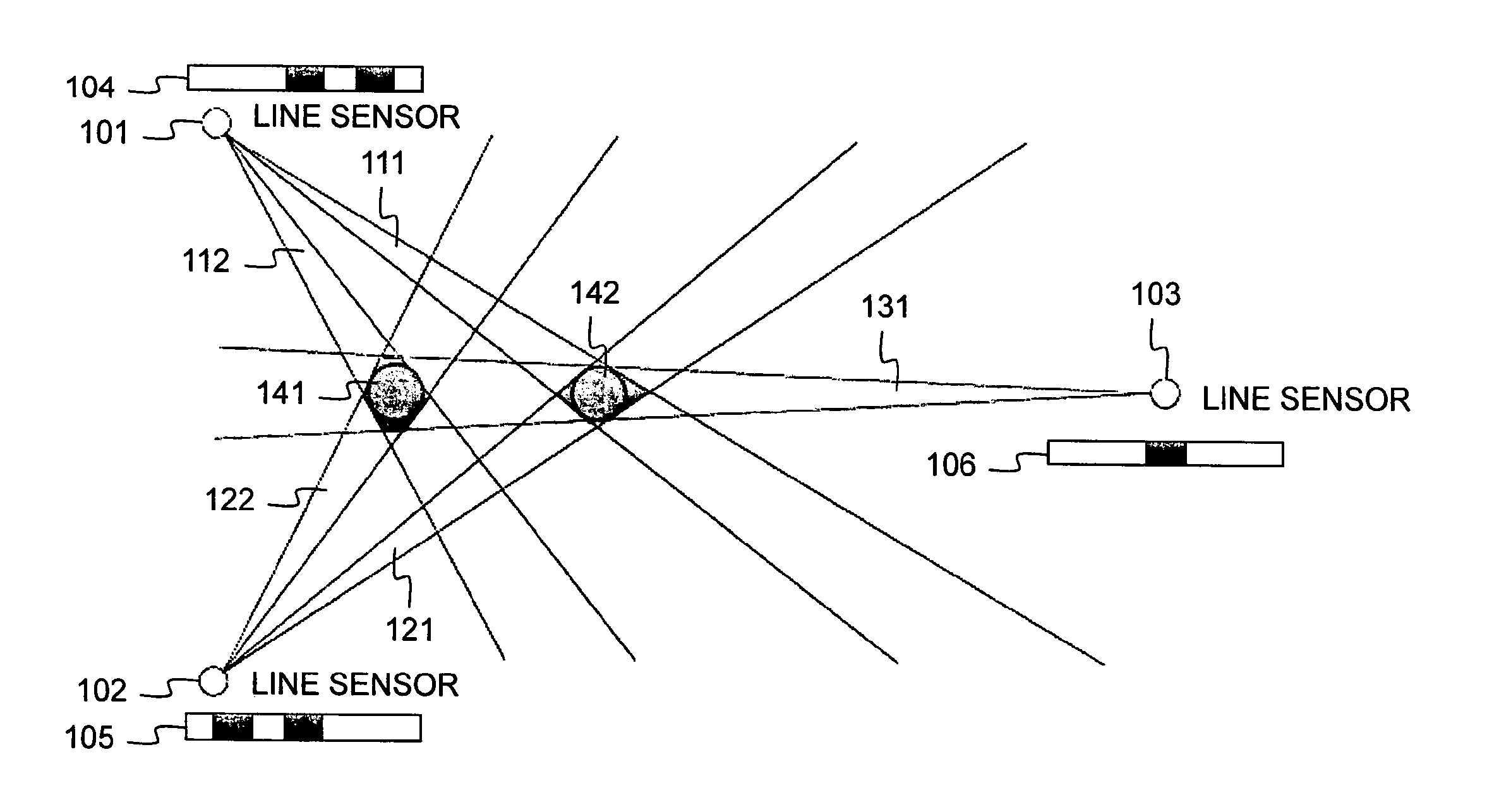
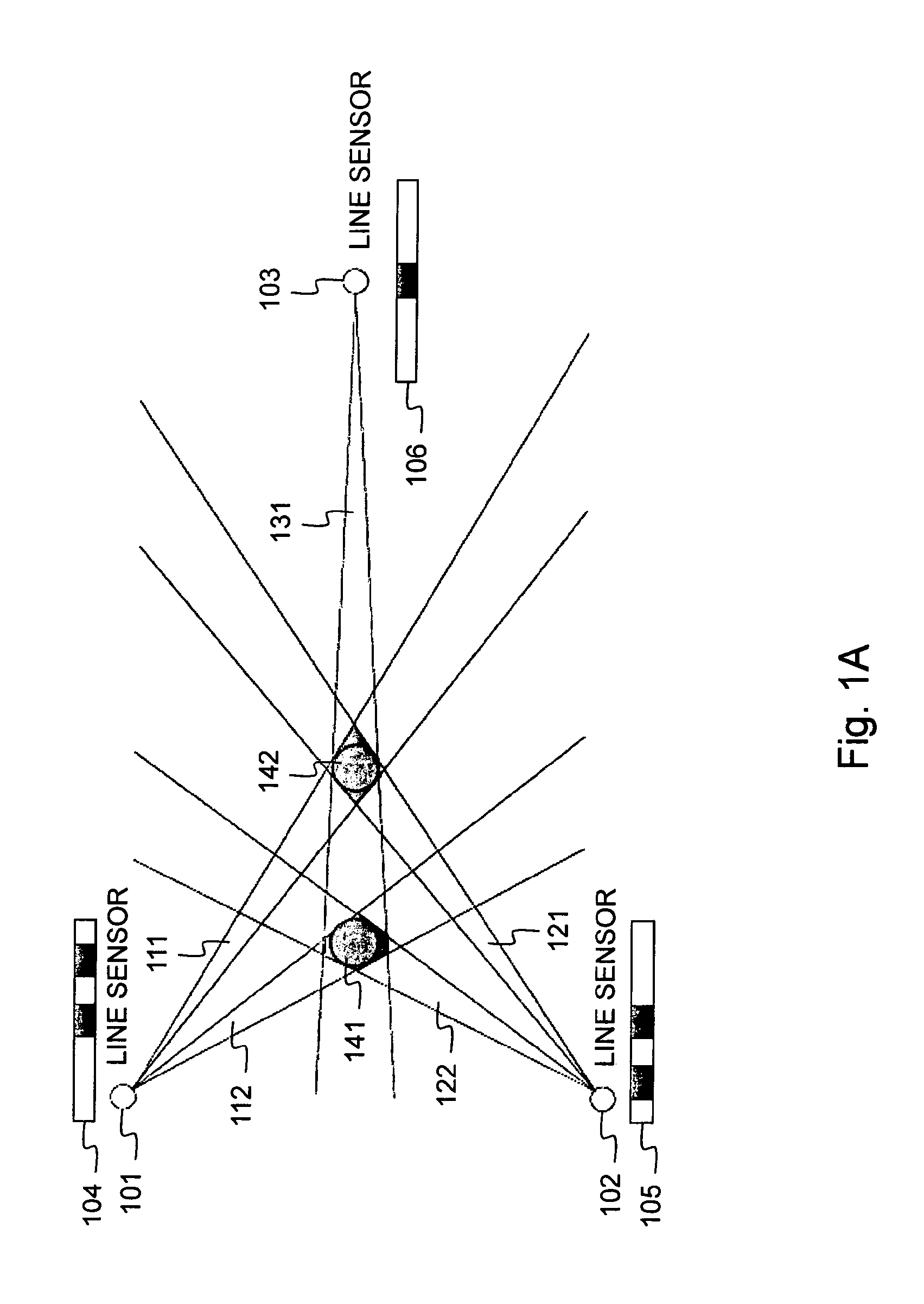
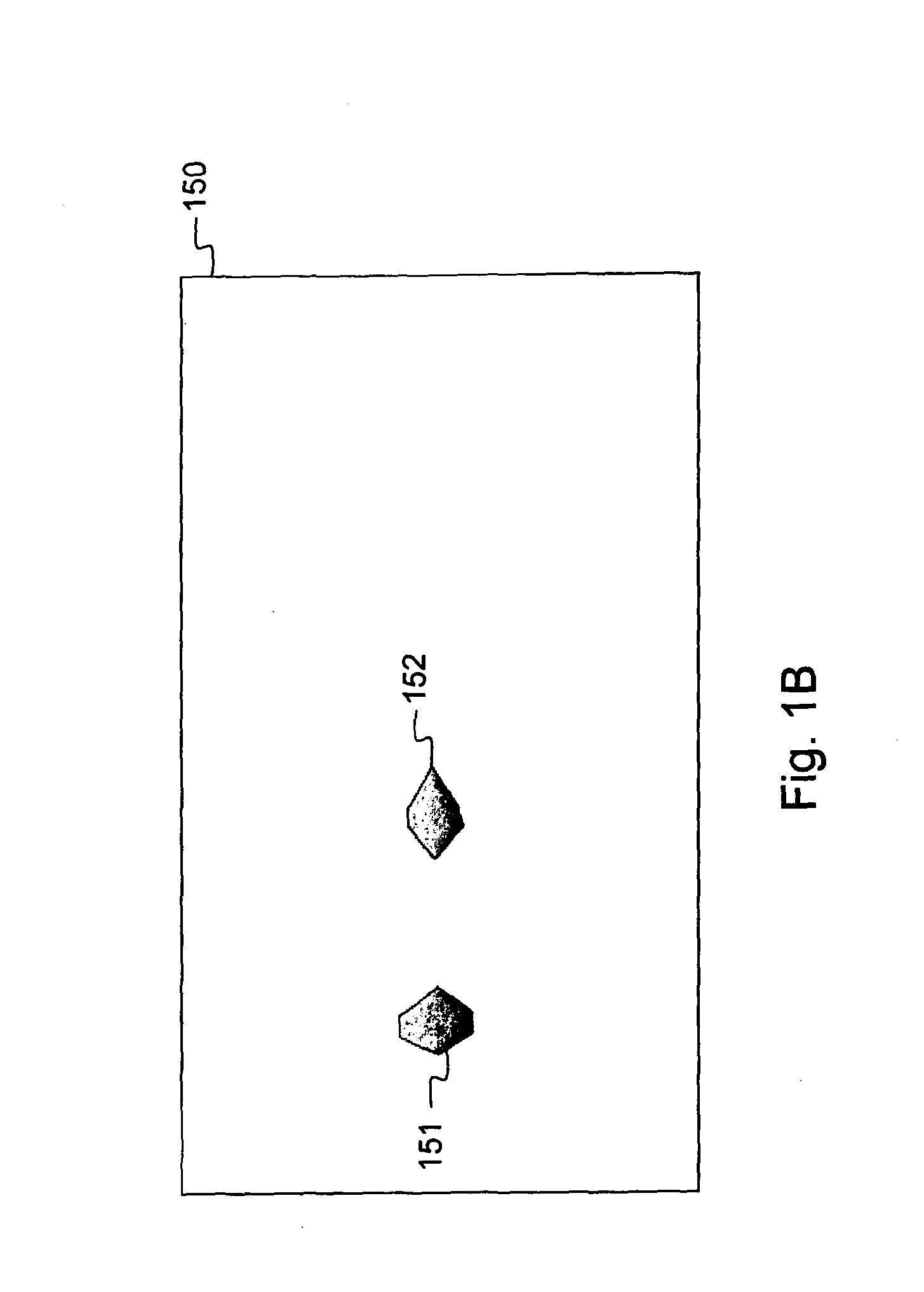
[0072]FIG. 1A shows an embodiment of the occupancy sensing system according to the invention that consists of three light integrating optical line sensors 101, 102 and 103. These light integrating optical line sensors 101, 102 and 103 are linear arrays of photodiodes that are positioned parallel to the ground plane at a height such that the persons or objects of interest are sensed, e.g. for persons at 150 cm from the ground plane. The light integrating line sensors 101, 102 and 103 include optical light integrating devices that consist of metal plates with a slit. This slit controls the re-projection frustum of each photodiode, i.e. the light that is integrated onto that photodiode. These re-projection frustums are centred along vertical planes. The re-projection frustum of a photodiode is centred along a vertical plane that contains the photodiode and the slit, which is the light integrating device. In FIG. 4, some of these re-projection frustums are shown in a 2D representation ...


PUM


Abstract

An optical system for occupancy sensing according to the invention includes a plurality of optical line sensors, each consisting of a linear array of light sensing elements; and an optical light integrating device that integrates light from rays with incidence angles subject to geometric constraints to be sensed by a light sensing element.

Description

FIELD OF THE INVENTION[0001]The present invention generally relates to occupancy sensing, i.e. establishing a view on the occupancy of a space by persons and / or objects, like for instance a two dimensional (2D) top view or side view of a scene in a room containing people and objects, or a three dimensional (3D) map of a scene by combination of several 2D views. Occupancy sensing is used for various applications such as surveillance, video conferencing, smart rooms, building automation, sport games analysis, pick-and-place machine vision, intelligent airbags for cars, etc. The current invention in particular concerns a way for occupancy sensing that is very accurate, non-intrusive such that sensed objects or persons do not have to be tagged with dedicated devices, privacy friendly, low-power consuming in order to be battery operable, fast and cost-efficient, and has no or little impact on existing infrastructure and aesthetics.BACKGROUND OF THE INVENTION[0002]Occupancy sensing system...

Claims


Application Information

Patent Timeline
IPC IPC(8): G01B11/14
CPCG01V8/20H05B37/0227G08B13/194G08B13/181H05B47/115Y02B20/40
Inventor MORBEE, MARLEENTESSENS, LINDA
Owner SENSO2ME
Learn More