Surge protective device
A surge protector and electrode 2 technology, applied in protection switches, emergency protection devices, parts of protection switches, etc., can solve the problems of tripping stuck, deterioration, arcing, etc. The effect of increased heat transfer rate and shortened tripping time
- Summary
- Abstract
- Description
- Claims
- Application Information
AI Technical Summary
Problems solved by technology
Method used
Image
Examples
Embodiment 1
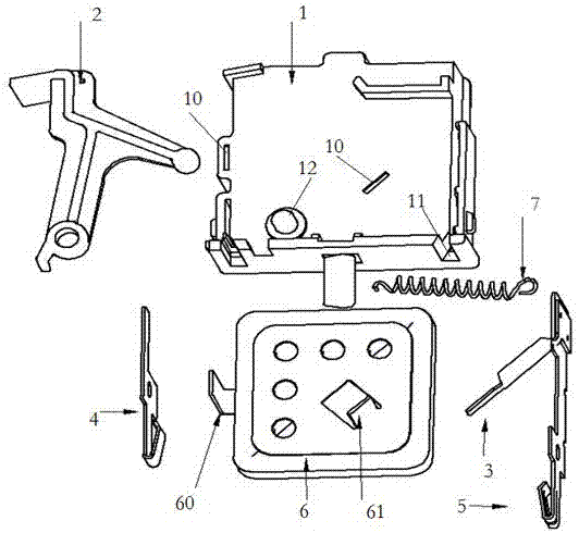
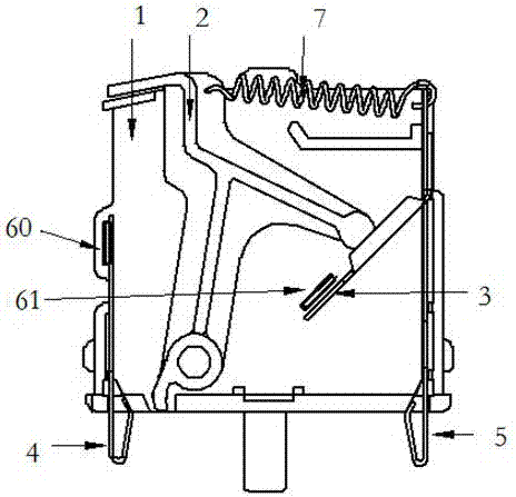
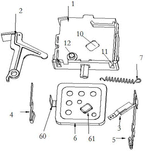
[0039] Such as image 3 As shown, what this embodiment protects is a surge protector, which includes a base 1, a trip bracket 2, a shrapnel 3, pin one 4, pin two 5, a varistor 6, a spring 7 and a shell body (not shown in the figure), the base 1 is provided with two electrode holes 10, two pin grooves 11 and a shaft 12, one electrode hole 10 is located at the lower right side of the base 1, and the other electrode hole 10 is located at the left side, The two pin slots 11 are respectively located on the left and right sides of the base 1 , the shaft 12 is located at the lower left of the base 1 , and the shell completely covers the base 1 .
[0040] The tripping bracket 2 has the same structure as the existing tripping bracket, and will not be described again.
[0041] Elastic piece 3 comprises elastic piece body 30, electrode two connecting portion 31 and pin two connecting portion 32, and elastic piece body 30 is provided with vertical spring angle 33, and electrode two conne...
Embodiment 2
[0048] This embodiment is basically the same as Embodiment 1, the difference is that the 7-position volute of the spring is installed on the shaft 12 , one end of the volute spring is connected to the shaft 12 , and the other end is connected to the trip bracket 2 .
Embodiment 3
[0050] This embodiment protects a surge protector, which includes a base 1, a shrapnel 3, a pin 4, a pin 2 5, a piezoresistor 6 and a housing (not shown in the figure), the base 1 There are two electrode holes 10, two pin slots 11 and a shaft 12, one electrode hole 10 is located at the lower right side of the base 1, the other electrode hole 10 is located at the left side, and the two pin slots 11 are respectively located at the left and right sides of the base 1 On both sides, the shaft 12 is located at the lower left part of the base 1 , and the shell completely covers the base 1 .
[0051] The varistor is provided with electrode 1 60 and electrode 2 61. After the varistor 6 is installed on the base 1, the shrapnel 3 and the electrode 2 61 are welded together by fusible metal, and the connection surface between the shrapnel 3 and the electrode 2 61 is a horizontal plane. Under the vertical elastic force of the elastic piece 3 , the elastic piece 3 and the second electrode 61...
PUM
 Abstract
Description
Claims
Application Information
 - R&D
- Intellectual Property
- Life Sciences
- Materials
- Tech Scout
- Unparalleled Data Quality
- Higher Quality Content
- 60% Fewer Hallucinations
Browse by: Latest US Patents, China's latest patents, Technical Efficacy Thesaurus, Application Domain, Technology Topic, Popular Technical Reports.
© 2025 PatSnap. All rights reserved.Legal|Privacy policy|Modern Slavery Act Transparency Statement|Sitemap|About US| Contact US: help@patsnap.com


