
Method and system for realizing Ethernet signal lock function

A technology of locking signals and Ethernet, applied in the field of communication, can solve the problems of increasing equipment software and hardware costs, and achieve the effect of reducing equipment hardware and software costs and improving user experience.

Active Publication Date: 2017-12-22
ZTE CORP
View PDF5 Cites 0 Cited by
  • Summary
  • Abstract
  • Description
  • Claims
  • Application Information

AI Technical Summary

Problems solved by technology

[0006] The main technical problem to be solved by the present invention is to provide a method and system for realizing the Ethernet locking signal function, and to solve the problem of increasing equipment software and hardware costs brought about by using a logic chip to realize the LCK function in the prior art

Method used


Image

  • Method and system for realizing Ethernet signal lock function
  • Method and system for realizing Ethernet signal lock function
  • Method and system for realizing Ethernet signal lock function

Examples


Embodiment 1

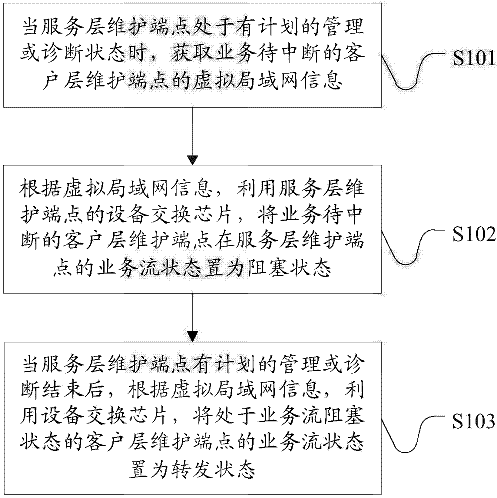
[0023] see figure 1 , this embodiment provides a method for the service layer MEP to interrupt the data traffic flow of a specific client layer in the client layer it serves when the service layer MEP is in a planned management or diagnosis state. In the method of this embodiment, the service The device switching chip of the layer maintenance endpoint blocks the service flow of the specific client layer served by the service layer maintenance endpoint, helping to realize the LCK function.

[0024] S101. When the service layer maintenance endpoint is in the planned management or diagnosis state, obtain the virtual local area network information of the client layer maintenance endpoint whose business is to be interrupted;

[0025] S102. According to the virtual local area network information, use the device switching chip of the service layer maintenance endpoint to set the service flow status of the service layer maintenance endpoint of the client layer maintenance endpoint who...

Embodiment 2

[0051] When troubleshooting, maintenance personnel generally perform maintenance operations on the service layer. Specifically, maintenance personnel need to select a maintenance endpoint from multiple maintenance endpoints as the locked maintenance endpoint in this maintenance according to the actual situation. Wherein, the maintenance endpoint belongs to the boundary endpoint of the maintenance domain. After the maintenance personnel selects the maintenance endpoint, since the service layer maintenance endpoint may serve multiple client layers, if the data services of the multiple client layer maintenance endpoints it serves are all blocked , when troubleshooting, the business congestion of multiple client layers will hinder troubleshooting. Thus, after the maintenance personnel have selected the maintenance endpoint of the service layer, they also need to further select which client layer is blocked. Generally speaking, for the convenience of management, VLANs (Virtual Local...

Embodiment 3

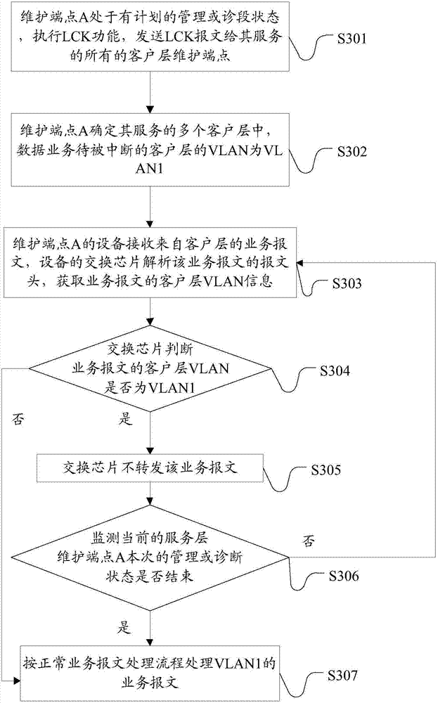
[0063]S401. If the maintenance endpoint of the service layer selected by the maintenance personnel is A, the VLANs to which the maintenance endpoint of the client layer of the A service belongs include VLAN1, VLAN2, and VLAN3. When the maintenance personnel selects the client layer corresponding to VLAN1 as the troubleshooting, the service is blocked. client layer, see Figure 4 , in the process of implementing the LCK function, the implementation steps of the service flow blocking of the client layer VLAN1 on the service node A are as follows:

[0064] S401. The maintenance endpoint A is in a planned management or diagnosis state, executes the LCK function, and sends LCK messages to all client layer maintenance endpoints served by it;

[0065] S402. The maintenance endpoint A determines that among the multiple client layers it serves, the VLAN of the client layer whose data service is to be interrupted is VLAN1;

[0066] S403. The switching chip determines that the VLAN of t...


PUM


Abstract

The invention discloses a method and a system for realizing an Ethernet signal lock function. The method comprises the following steps of utilizing a device switching chip on a maintenance association end point of a service layer to block service flow of a maintenance association end point of a client layer of a to-be-interrupted service when the maintenance association end point of the service layer is in a planned management or diagnosis state; and when management or diagnosis of the maintenance association end point of the service layer is completed, utilizing the device switching chip to forward the service flow of the maintenance association end point of the client layer in order to realize a state change of the service flow of the client layer from blockage to forwarding. According to the method and the system, the device switching chip is utilized to realize control of the state of the service flow of the maintenance association end point of the client layer; compared with a way of utilizing the added logical chip or the simplified logic chip in the device to realize the state of the service flow at the maintenance association end point of the client layer in the prior art, the method and the system do not need other chips, the service flow of the client layer can be interrupted through the switching chip on the existing device to help to realize the LCK function, the user experience is improved, and the device hardware and software costs are reduced.

Description

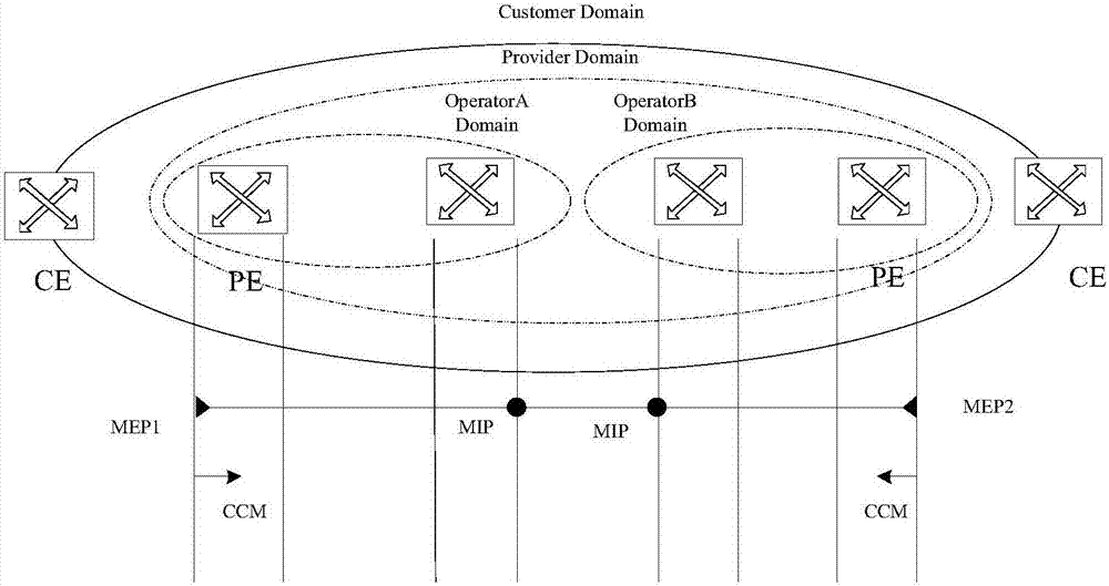
technical field [0001] The invention relates to the technical field of communication, in particular to a method and a system for realizing the function of an Ethernet locking signal. Background technique [0002] At present, Ethernet, with its attractive advantages such as simplicity, low cost, high scalability, and good support for burst traffic, has made traditional telecommunication networks gradually develop towards Ethernet, and Ethernet has replaced SDH (Synchronous Digital Hierarchy, Synchronous digital system) has become the trend of the times. However, Ethernet still has many shortcomings, one of which is poor manageability. [0003] In order to manage the network, the entire network is divided into many maintenance domains. The maintenance domain has a boundary, and its boundary is each port. Therefore, it is enough to configure an entity on the boundary port. This entity is called a maintenance endpoint ( Maintenance association End Point or MEP). The boundary ...

Claims


Application Information

Patent Timeline
Patent Type & Authority Applications(China)
IPC IPC(8): H04L12/937
CPCH04L49/253
Inventor 马焕君裴玉塔
Owner ZTE CORP
Learn More