Rotatable multi-direction ironing platform for ready-made clothes

An ironing platform and rotary technology, which is applied in the field of ready-made garments, can solve the problems of easily bulging on the surface, secondary wrinkles, and indentation of clothes, so as to reduce equipment occupation, avoid secondary wrinkles, and achieve multifunctional functions. Effect

Inactive Publication Date: 2018-11-13
安徽京威纺织服饰有限公司
0 Cites 0 Cited by

AI-Extracted Technical Summary

Problems solved by technology

For example, an adjustable radian clothing ironing device disclosed in patent application 201610398404X, the ventilation holes are arranged on the ironing surface. ...

Method used

Because the working principle of the first air outlet 153 and the second air outlet 154 of the present invention are the same, the present invention takes the first air outlet 153 as an example to introduce the principle, and the principle of blocking the second air outlet 154 refers to blocking the first air flow Rationale for exit 153. In the present invention, by turning the screw 161 inward, the rubber head 171 blocks a section of the airflow channel 151 that communicates with the first airflow outlet 153, so as to block the first airflow outlet 153. By rotating the screw 161 outward, the The rubber head 171 unblocks a section of the airflow channel 151 that communicates with the first airflow outlet 153 . The screw groove provided in the ironing board 1 of the present invention is used to cooperate with the screw rod 161. The inside of the screw groove is close to the position of the air flow channel 151. The shape and size of the storage cavity that match the shape and size of the rubber head 171 are provided. When the rubber head When the rubber head 171 is not used to block the channel, the rubber head 171 is completely housed in the housing cavity. Such a variable-diameter screw groove setting can ensure that the rubber head 171 moves back and forth while ensuring its sufficient sealing performance. When the rubber head 171 blocks the channel, the part of the rubber head 171 is preferably still limited in the receiving cavity, preventing airflow from leaking out of the screw groove.
The present invention turns over to different positions by the ironing board 1, satisfies different ironing process requirements, realizes fast fastening by fasteners of the present invention, and integrates traditional flat ironing and hanging ironing on one device , to achieve the technical effects of multifunctional equipment, high integration, and reduced equipment footprint and cost. The setting of the opening groove 221 structure of the present invention can meet the requirement that the ironing board 1 can be moved forward for a certain distance before it rotates from the horizontal state to the vertical state. Ironing plate 1 is too narrow and affects the smooth progress of rotation. Since the fastening of the present invention is realized by the insertion and engagement of the fasteners and the support frame 2, this fastening method can achieve high-efficiency, fast and convenient technical effects. In the present invention, the upper part of the vertical plate 21 is provided with an arc-shaped opening groove 211. On the one hand, the arc-shaped opening groove 211 can provide the installation point of the front fastener 41, and on the other hand, it can play a role in the precise rotation of the ironing board 1. to positioning orientation.
[00...

Abstract

The invention discloses a rotatable multi-direction ironing platform for ready-made clothes. The ironing platform comprises an ironing plate and a support frame, wherein the ironing plate is pivoted with the support frame through fasteners, one of the upper and lower surfaces of the ironing plate is a curved surface, and the other surface is a horizontal plane; hangers are arranged on the horizontal plane; two groups of the fasteners are symmetrically arranged on the left and right sides of the ironing plate; each group of the fasteners comprise a front-mounted fastener and a rear-mounted fastener, the front-mounted fastener is located at the front end of the ironing plate, and the rear-mounted fastener is located at the rear end of the ironing plate; and arc-shaped open slots and insertion slots are formed in the upper parts of vertical plates, and one relatively lower ends of the arc-shaped open slots upwards extend close to the rear ends of the vertical plates in an arc manner fromthe front ends of the vertical plates. The rotatable multi-direction ironing platform has the advantages that flat ironing and suspension ironing can be realized, the integration effect of the platform is strong, and the versatility of the platform is improved.

Application Domain

Ironing boardsIroning apparatus +2

Technology Topic

FastenerEngineering

Image

  • Rotatable multi-direction ironing platform for ready-made clothes
  • Rotatable multi-direction ironing platform for ready-made clothes
  • Rotatable multi-direction ironing platform for ready-made clothes

Examples

  • Experimental program(5)

Example Embodiment

[0035] Example 1
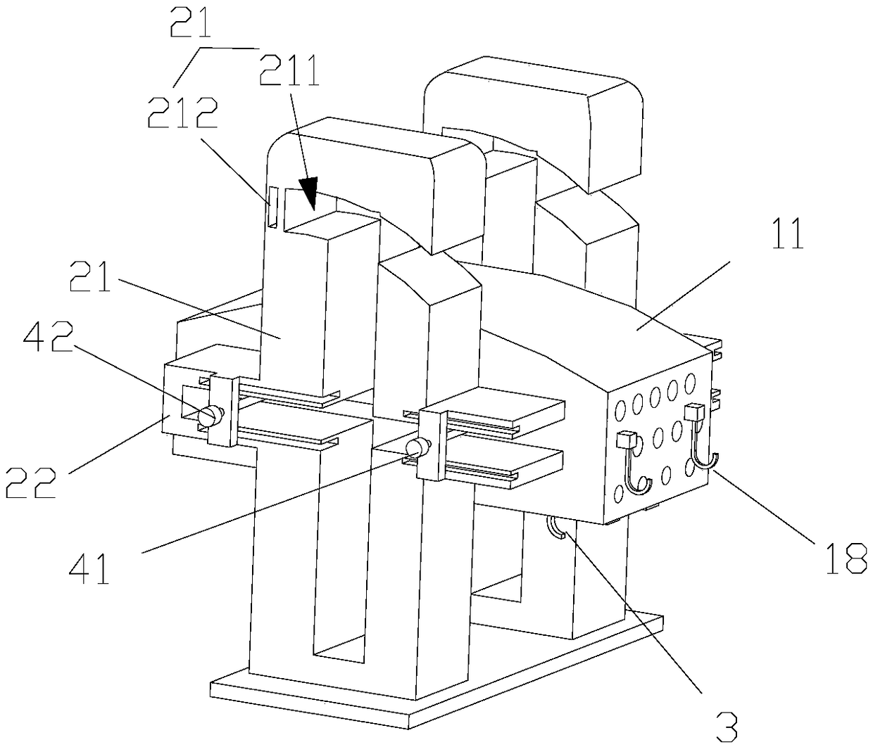
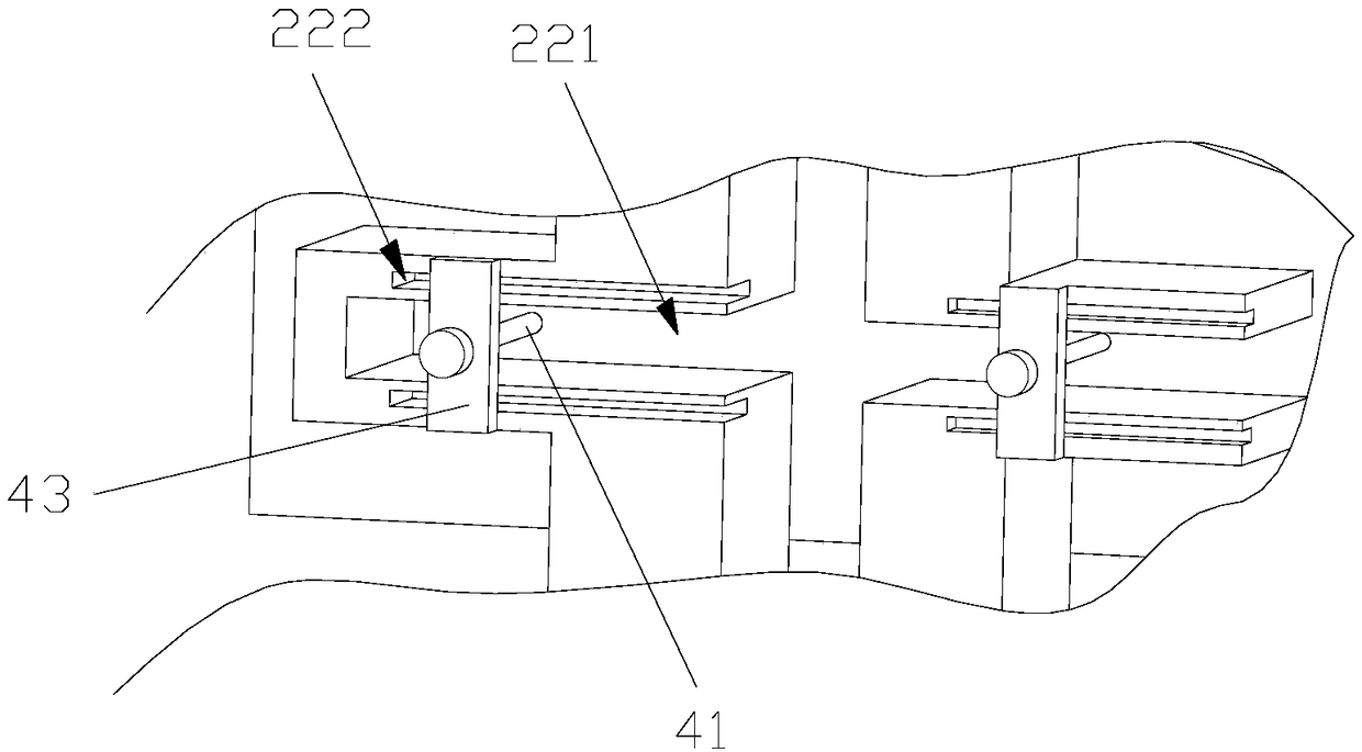
[0036] Such as figure 1 , 2 As shown, the present invention discloses a rotatable multi-directional ironing platform for garments, which includes an ironing board 1 and a supporting frame 2, and the ironing board 1 is pivotally connected to the supporting frame 2 by fasteners. One of the upper and lower surfaces of the ironing board 1 is a curved surface 11 and the other is a horizontal surface 12. A first hook 3 is provided on the horizontal surface 12. The support frame 2 includes support columns symmetrically arranged on the left and right sides of the ironing board 1. Each support column has a cross structure and includes a vertical plate 21 and a horizontal plate 22. Such as image 3 As shown, the horizontal plate 22 is provided with an opening groove 221 and a sliding groove 222 parallel to the opening groove 221. The guiding direction of the opening groove 221 is parallel to the length direction of the horizontal plate 22 and the starting end of the opening groove 221 is from a position close to the horizontal plate 22. The rear end starts to extend horizontally forward, and penetrates the vertical plate 21 until it extends to the front end of the horizontal plate 22. The length of the sliding groove 222 is at least the same as the length of the opening groove 221 and the sliding groove 222 extends beyond the front end of the horizontal plate 22. Two sets of fasteners are symmetrically arranged on the left and right sides of the ironing board 1. Each set of fasteners includes a front fastener 41 and a rear fastener 42. The front fastener 41 is located at the front end of the ironing board 1, and the rear fastener 42 is located at the rear end of the ironing board 1. .
[0037] Since the front fastener 41 and the rear fastener 42 of the present invention have the same structure, the present invention takes the front fastener 41 as an example to introduce the structure, and the structure of the rear fastener 42 refers to the front fastener 41 Structure. The front fastener 41 includes a connecting shaft 411, a bearing 412, and an inserting block 413. The bearing 412 is installed in the middle of the side of the ironing board 1, one end of the connecting shaft 411 is connected to the bearing 412, and the other end of the connecting shaft 411 extends The opening slot 221 is connected to the insert block 413, and the insert block 413 can be inserted into the sliding slot 222. The upper part of the vertical plate 21 is provided with an arc-shaped opening groove 211 and a slot 212, and the lower end of the arc-shaped opening groove 211 extends upward in an arc shape from the front end of the vertical plate 21 until it is close to the rear end of the vertical plate 21 . The ironing board 1 turns upwards with the rear fastener 42 as the center, which can drive the front fastener 41 to slide along the guide track of the arc-shaped opening groove 211 from the front end of the arc-shaped opening groove 211 to the rear end of the arc-shaped opening groove 211 , And the inserting block 413 in the rear fastener 42 can be inserted into the slot 212.
[0038] When flat ironing is required, the ironing board 1 of the present invention is rotated to a horizontal shape with the curved surface 11 upward, and the insert block 413 in the front fastener 41 and the insert block 413 in the rear fastener 42 They are respectively inserted into the sliding grooves 222, so that the ironing board 1 and the support frame 2 are fixed, the clothes are spread flat on the curved surface 11, and the iron is used for horizontal ironing.
[0039] Such as Figure 4 As shown, when it is necessary to hang ironing, move the insert block 413 in the front fastener 41 and the insert block 413 in the rear fastener 42 to a position where it leaves the chute 222, and move the ironing board 1 horizontally until The rear fastener 42 is completely extended from the front end of the opening groove 221, the insert 413 of the rear fastener 42 is inserted into the sliding groove 222, and the ironing board 1 is rotated until it is in a vertical state. At this time, the front fastener 41 moves into the arc-shaped opening groove 211, and then the insert block 413 in the front fastener 41 is inserted into the slot 212 to complete the fixing of the ironing board 1 and the support frame 2. The clothes are hung on the first hook 3 of the horizontal surface 12, and then an iron is used for hanging ironing.
[0040] In the present invention, the ironing board 1 is turned over to different positions to meet the requirements of different ironing processes. The fasteners of the present invention realize fast fastening, integrate the traditional flat ironing and hanging ironing into one device, and achieve The technical effect of equipment function diversity, high integration, and reduction of equipment occupation and cost. The structure of the opening slot 221 of the present invention can meet the requirement that the ironing board 1 can move forward a certain distance before rotating from the horizontal state to the vertical state. In this way, it can prevent the ironing board 1 from being too long or ironing. The ironing board 1 is too narrow to affect the smooth progress of the rotation. Since the fastening of the present invention is realized by inserting the fasteners and the support frame 2, the fastening method can achieve the technical effect of high efficiency, speed and convenience. The vertical plate 21 of the present invention is provided with an arc-shaped opening groove 211 on the upper part. On the one hand, the arc-shaped opening groove 211 can provide the installation point of the front fastener 41, and on the other hand, it can effectively rotate the ironing board 1 To the positioning and guiding role.
[0041] In some embodiments, the sliding groove 222 includes an upper sliding groove 222 and a lower sliding groove 222 respectively located on the upper and lower sides of the opening groove 221. Two ends of the insert block 413 can be inserted into the upper chute 222 and the lower groove 222 respectively, wherein one end of the insert block 413 in the front fastener 41 can be inserted into the slot 212. The arrangement of the upper and lower slide grooves 222 can further improve the stability of the ironing board 1 when it is fastened.

Example Embodiment

[0042] Example 2
[0043] Such as Figure 8-10 As shown, the difference between this embodiment and the above-mentioned embodiment is that the connecting shaft 411 is a screw rod, and the inserting block 413 is matched with the connecting shaft 411 through a screw sleeve (not shown in the figure). Or, the inserting block 413 is in clearance fit with the connecting shaft 411, and the upper clamping spring plate 213 and the lower clamping spring plate 214 arranged in the vertical direction are arranged in the sliding groove 222 and the slot 212, and the end of the inserting block 413 can clamp It is held between the upper clamping spring plate 213 and the lower clamping spring plate 214.
[0044] When the connecting shaft 411 is a screw rod, the insertion block 413 can be moved along the axial direction of the connecting shaft 411 by rotating the other side of the screw rod, so that the insertion block 413 and the sliding groove 222 and the slot 212 can be checked or separated. When the connecting shaft 411 is a guide shaft, the inserting block 413 can move freely on the connecting shaft 411. In order to increase the resistance of its movement, a rubber sleeve can be sleeved on the connecting shaft 411 to increase the sliding resistance of the inserting block 413. When the end of the insert block 413 is inserted into the sliding groove 222 and the slot 212, the upper clamping spring plate 213 and the lower clamping spring plate 214 move back under force, and clamp the end of the insert 413 on the upper clamp Between the holding spring plate 213 and the lower holding spring plate 214, the insertion block 413 is fixed. The upper clamping spring plate 213 and the lower clamping spring plate 214 of the present invention are preferably limited in the depths of the sliding groove 222 and the slot 212, so that when the ironing board 1 needs to be translated, the insert 413 does not need to be completely Move out of the sliding groove 222, therefore, the inserting block 413 can always be limited in the sliding groove 222, providing support and guiding for the sliding groove 222, and ensuring stable translation.

Example Embodiment

[0045] Example 3
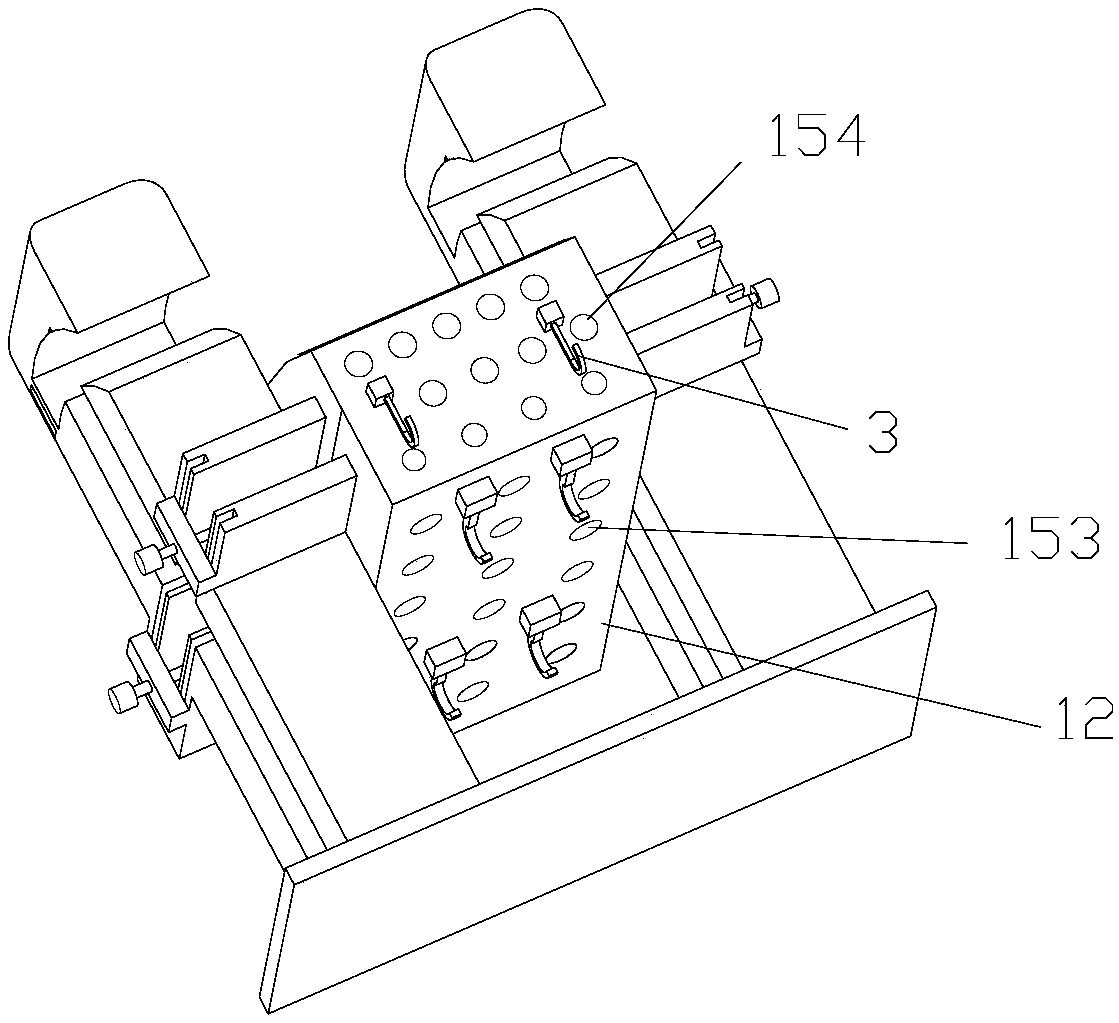
[0046] Such as figure 2 , 6 , 7, and 11, the difference between this embodiment and the above-mentioned embodiment lies in: an air flow channel 151 is provided in the inner cavity of the ironing board 1, and an air inlet (not shown in the figure) is provided on the surface of the ironing board 1. Draw out), a first air outlet 153 is provided on the horizontal plane 12, and a second air outlet 154 is provided on both the front and rear sides of the ironing board 1. The air inlet, the first air outlet 153 and the second air outlet 154 are all connected to the air channel 151. Second hooks 18 are also provided on the front and rear surfaces of the ironing board 1. It also includes a first sealing element (not shown in the figure) for blocking the first air outlet 153, and a second sealing element (not shown in the figure) for blocking the second air outlet 154.
[0047] After ironing, the clothes need to be dried to control their moisture regain. The invention uses air blowing to take away the water vapor on the clothes surface. Specifically, after flat ironing, the ironed clothes are hung on the second hooks 18 on the front and rear surfaces of the ironing board 1, and the first airflow outlet 153 is blocked by the first sealing member, and the hot air is blocked from entering The air port is poured in, and flows out from the second air outlet 154, sprayed onto the clothes, and takes away the water vapor. In the same way, after hanging ironing, the second airflow outlet 154 is blocked by the second sealing member, hot air is poured in from the air inlet, and out of the first airflow outlet 153, sprayed onto the clothes, taking away water vapor. Compared with the prior art, the present invention adopts suspended air-jet drying instead of induced-air ironing drying in the prior art. Compared with the prior art, it does not need to provide vent holes on the curved surface 11 of the ironing board 1 and avoids secondary wrinkles caused by flat drying. And the existence of vents leads to insufficient ironing flatness. With the hanging air-jet drying method of the present invention, the clothes do not need to directly contact the ironing board 1, and the hanging drying will not cause secondary wrinkles. In addition, since the first air outlet 153 and the second air outlet 154 of the present invention are arranged in a matrix, multiple areas of the clothes can be dried continuously and simultaneously. The present invention does not need to be equipped with a separate blower, and does not need to move the blower to achieve clothing Blow dry.
[0048] In some embodiments, each sealing element includes a screw 161 and a rubber head 171. The outer end of the screw 161 extends out of the ironing board 1, the inner end of the screw 161 extends into the ironing board 1 in a threaded manner, and the rubber head 171 is connected to the end of the inner end of the screw 161. The inward movement of the inner end of the screw 161 can drive the rubber head 171 to block the air flow channel 151.
[0049] Since the working principle of blocking the first air outlet 153 and the second air outlet 154 of the present invention is the same, the present invention takes the blocking of the first air outlet 153 as an example to introduce the principle. The principle of blocking the second air outlet 154 refers to the principle of blocking the first air outlet 153. principle. In the present invention, by rotating the screw 161 inwardly, the rubber head 171 blocks a section of the airflow channel 151 that communicates with the first airflow outlet 153 to achieve the effect of blocking the first airflow outlet 153. By rotating the screw 161 outward, The rubber head 171 unblocks a section of the airflow channel 151 communicating with the first airflow outlet 153. The screw groove opened in the ironing board 1 of the present invention to cooperate with the screw 161, the inner side of the screw groove is opened at a position close to the airflow channel 151, and the shape and size of the accommodating cavity coincides with the shape and size of the rubber head 171. When the 171 is not used to block the passage, the rubber head 171 is completely accommodated in the receiving cavity. Such a variable-diameter screw groove arrangement can ensure that the rubber head 171 moves back and forth while ensuring its full sealing. When the rubber head 171 blocks the channel, the part of the rubber head 171 is preferably still limited in the receiving cavity to prevent the airflow from leaking from the screw groove.

PUM

no PUM

Description & Claims & Application Information

We can also present the details of the Description, Claims and Application information to help users get a comprehensive understanding of the technical details of the patent, such as background art, summary of invention, brief description of drawings, description of embodiments, and other original content. On the other hand, users can also determine the specific scope of protection of the technology through the list of claims; as well as understand the changes in the life cycle of the technology with the presentation of the patent timeline. Login to view more.

Similar technology patents

Intelligent express item management system with error detection function and control method of intelligent express item management system

ActiveCN106391484AHighly integratedStrengthen comprehensive management
Owner:紫光智云(江苏)物联网科技有限公司

Novel integrated feed particle production equipment

PendingCN114130506AFunctionalFunctional diversity
Owner:芦东洋

Watchdog circuit capable of configuring dog-feeding cycle

PendingCN106528319AMeet the delay requirementHighly integrated
Owner:山东有人物联网股份有限公司

Auxiliary system for diesel engine

ActiveCN101922344AHighly integratedAuxiliary pipeline less
Owner:CHONGQING PUSH MECHANISM

Intelligent electrical valve locator main board hardware circuit

InactiveCN103343831AHighly integratedgood suppression effect
Owner:TIANJIN JINGTONG CONTROL INSTR TECH

Classification and recommendation of technical efficacy words

Why Eureka
Try Eureka