Surface cleaning machine

A cleaning machine and cleaning head technology, which is applied to cleaning equipment, suction nozzles, vacuum cleaners, etc., can solve the problems that the cleaning head cannot realize the universal rotation, the cleaning roller is difficult to disassemble and clean, and the cleaning roller cannot be cleaned automatically, so as to save the cleaning head Space, simple structure, strong water and dirt absorption performance

Inactive Publication Date: 2017-12-26
GUANGDONG BARSETTO ELECTRIC IND CO LTD
View PDF9 Cites 3 Cited by
  • Summary
  • Abstract
  • Description
  • Claims
  • Application Information

AI Technical Summary

Problems solved by technology

[0002] Some cleaning heads of existing cleaning machines are composed of multiple suction ports, resulting in complex structure, poor water absorption and dirt absorption performance; It can absorb dust or dirt, but cannot clean the surface of components like a rag; some cleaning rollers cannot be cleaned automatically; some cleaning rollers are difficult to disassemble and wash; and some cleaning heads cannot achieve universal rotation
Patent Publication No. CN10673910A and Patent Publication No. CN106793900A respectively disclose a surface cleaning machine, both of which use two suction ports and two suction channels. , resulting in poor water and dirt absorption performance

Method used


Image

  • Surface cleaning machine
  • Surface cleaning machine
  • Surface cleaning machine

Examples


Embodiment Construction

[0024] The technical solutions of the present invention will be described below in conjunction with the accompanying drawings and embodiments.

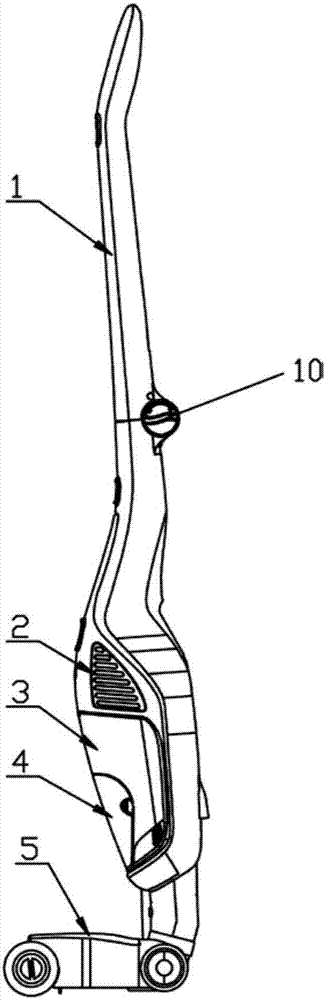
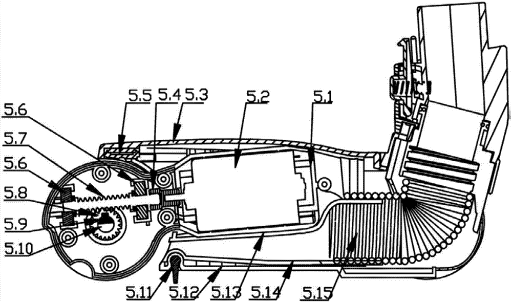
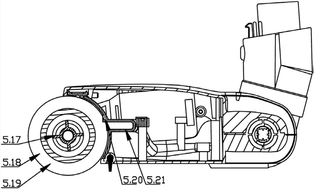
[0025] Such as Figure 1 to Figure 3 As shown, a surface cleaning machine according to the present invention includes a suction device assembly 2 fixed on a handle assembly 1, a dirt collection box assembly 3, a cleaning liquid assembly 4 and a cleaning head assembly 5, and the cleaning head assembly 5 includes a cleaning head The upper cover 5.3 is connected with the bottom cover 5.12 of the cleaning head, the upper cover 5.3 of the cleaning head is connected with the bottom cover 5.12 of the cleaning head, and a cavity is formed, and a cleaning roller mechanism, a rotary driving mechanism and a suction channel 5.15 are arranged in the cavity, and the cleaning roller The mechanism is driven to rotate by a rotary drive mechanism, the rotary drive mechanism is arranged side by side with the suction channel 5.15, and the rotary drive mo...


PUM


Abstract

The invention relates to the technical field of cleaning equipment, in particular to a surface cleaning machine. The surface cleaning machine comprises a pumping and suction device component, a dirt collecting box component, a cleaning solution component and a cleaning head assembly, the pumping and suction device component, the dirt collecting box component, the cleaning solution component and the cleaning head assembly are fixed to the handle assembly, the cleaning head assembly comprises a cleaning head upper cover and a cleaning head bottom cover, the cleaning head upper cover is correspondingly connected with the cleaning head bottom cover, a cavity is formed and is internally provided with a cleaning roller mechanism, a rotary driving mechanism and a pumping and suction channel, the cleaning roller mechanism drives rotation through the rotary driving mechanism, the rotary driving mechanism and the pumping and suction channel are arranged side by side, a rotary driving motor of the rotary driving mechanism is arranged at the upper end or the lower end of the pumping and suction channel, the handle assembly is provided with a cleaning machine starting switch, and the pumping and suction device component and the rotary driving mechanism are started and closed through the cleaning machine starting switch respectively. By making the rotary driving mechanism and the pumping and suction channel arranged side by side and making the rotary driving motor arranged at the upper end or the lower end of the pumping and suction channel, the width of the pumping and suction channel is effectively guaranteed, and the water suction and dirt suction performance is high.

Description

technical field [0001] The invention relates to the technical field of cleaning equipment, in particular to a surface cleaning machine. Background technique [0002] Some cleaning heads of existing cleaning machines are composed of multiple suction ports, resulting in complex structure, poor water absorption and dirt absorption performance; It can absorb dust or dirt, but cannot clean the surface of the component like a rag; some cleaning rollers cannot be cleaned automatically; some cleaning rollers are difficult to disassemble and wash; and some cleaning heads cannot achieve universal rotation. Patent Publication No. CN10673910A and Patent Publication No. CN106793900A respectively disclose a surface cleaning machine, both of which use two suction ports and two suction channels. , resulting in poor water absorption and dirt absorption performance. Contents of the invention [0003] In view of the above problems, the present invention provides a surface cleaning machine,...

Claims


Application Information

Patent Timeline
Patent Type & Authority Applications(China)
IPC IPC(8): A47L9/04
CPCA47L9/04A47L9/0411
Inventor 郭建刚韩玉臣申清华
Owner GUANGDONG BARSETTO ELECTRIC IND CO LTD
Why Eureka
Try Eureka