Urethral catheterization device for urology department

A urine device and urology technology, applied in the direction of catheters, balloon catheters, hypodermic injection devices, etc., can solve the problems of increasing urine, discharging bladder, damage, etc., and achieve the effect of reducing cost expenditure and preventing pollution

Inactive Publication Date: 2017-12-26
耿俐
View PDF4 Cites 6 Cited by
  • Summary
  • Abstract
  • Description
  • Claims
  • Application Information

AI Technical Summary

Problems solved by technology

[0003] The urination hole of the existing urinary catheter is opened at the front end of the balloon, and the balloon is located at the bottom of the bladder to fix the catheter. Due to the position of the urination hole, the patient cannot drain the bladder at the bottom of the bladder when the patient is drained by the catheter. urine excretion resulting

Method used


Image

  • Urethral catheterization device for urology department
  • Urethral catheterization device for urology department
  • Urethral catheterization device for urology department

Examples


Embodiment 1

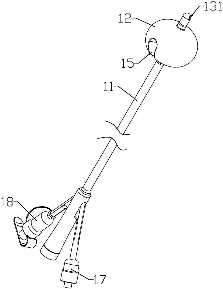
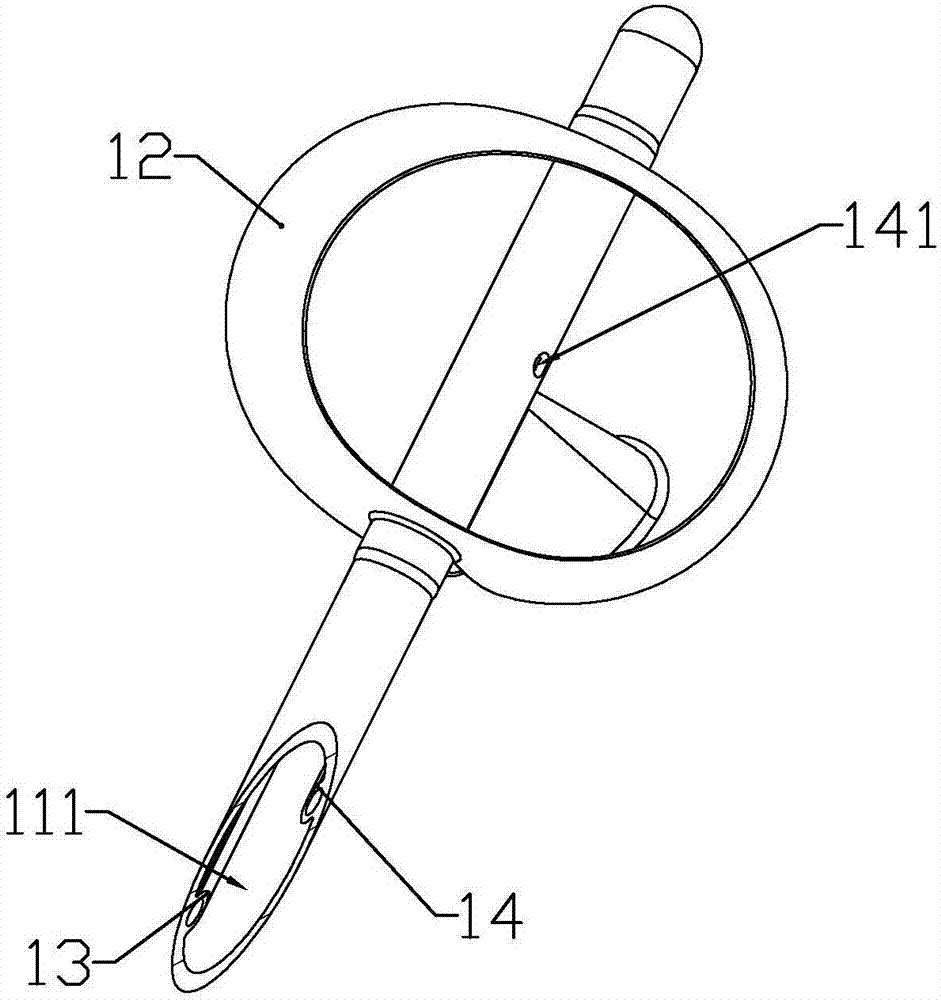
[0032] according to Figure 1 to Figure 5 As shown, a urological catheterization device described in this embodiment includes a catheter 1, a front connecting tube 31 plugged in at the end of the catheter, a normally closed tube sleeved at the rear end of the front connecting tube. The connecting assembly 2, the rear connecting pipe 32 plugged in the rear end of the normally closed connecting assembly, and the drainage bag 33 inserted in the rear end of the rear connecting pipe.

[0033]The catheter includes a drainage tube 11; a drainage cavity 111 for drainage is formed in the drainage tube; a spherical end 16 for closing the drainage cavity is formed at the front end of the drainage tube; the front part of the drainage tube is located at A balloon 12 is formed behind the end; when the balloon is not filled with water, it is closely attached to the outer wall of the drainage tube, and when the balloon is filled with water, the balloon is inflated due to the water pressure in...

Embodiment 2

[0048] combine Figure 6 As shown, the present embodiment has made the following improvements on the basis of Embodiment 1; the outer side of the rear pipe is symmetrically formed with a convex tube 227 corresponding to the branch pipe; the length of the convex tube is from the film coating to the highest point to the distance between the head tubes.

[0049] When the patient needs to be continuously drained, the buckle is reversely buckled, that is, the lower extension is located above the convex tube, and since the end of the convex tube is against the lower extension, the The lower electrode is in continuous contact with the upper electrode, so that the pressing part is continuously pressed by the pressing head, so that the liquid collection chamber and the rear tube are in a continuous conduction state, thereby continuously draining the patient .

[0050] After the continuous drainage process is completed, the buckle is re-fastened to the initial state, that is, the lowe...


PUM


Abstract

The invention discloses a urethral catheterization device for the urology department. The device comprises a urinary catheter, a front connecting pipe connected to the tail end of the urinary catheter in an inserted mode, a normally-closed connecting component connected to the rear end of the front connecting pipe in a sleeved mode, a rear connecting pipe connected to the rear end of the normally-closed component in an inserted mode and a drainage bag connected to the rear end of the rear connecting pipe in an inserted mode. When a sacculus makes contact with the inner surface of a bladder, a urination hole cannot be blocked, and urine in the bladder cannot make the urine left in the bladder of a patient due to the fact that the position of the urination hole is higher than that of the sacculus; a film is raised through pressure in a liquid collecting cavity, flow of the urine inside a pipe body is indirectly controlled between the liquid collecting cavity and a rear pipe through channel conduction, and then the bladder function of the patient is exercised, and the patient does not need to regularly and manually control the connecting pipe of the drainage bag to exercise the bladder function.

Description

technical field [0001] The invention belongs to the field of medical devices, in particular to a urological catheterization device. Background technique [0002] Urinary catheter is one of the commonly used medical devices in clinical medicine such as urology. The catheter can be inserted into the bladder through the urethra to drain urine out. After the catheter is inserted into the bladder, a balloon near the tip of the catheter remains in the bladder. The urinary catheter is internally fixed so that the catheter is not easy to come out, and the urine is collected by connecting the drainage bag. [0003] The urination hole of the existing urinary catheter is opened at the front end of the balloon, and the balloon is located at the bottom of the bladder to fix the catheter. Due to the position of the urination hole, the patient cannot drain the bladder at the bottom of the bladder when the patient is drained by the catheter. Urinary excretion results in residual urine. ...

Claims


Application Information

Patent Timeline
IPC IPC(8): A61M1/00A61M25/10A61M39/22
CPCA61M25/0043A61M25/0068A61M25/10A61M39/22A61M2205/3331A61M2205/3382A61M2205/36A61M2210/1085A61M1/70A61M1/84A61M1/86A61M2210/005
Inventor 胡玥
Owner 耿俐
Why Eureka
Try Eureka