
An Asymmetric Coupling Mechanism with Two Rotations and One Shift

An asymmetric coupling and coupling rod technology, which is applied in the direction of manipulators, program-controlled manipulators, manufacturing tools, etc., can solve the lack of synthesis and research on the coupling mechanism of the two-rotation-one-movement kinematics, the lack of control accuracy of the position and attitude of the moving platform, and the lack of drive pairs. Problems such as large force, to achieve the effect of simplified kinematics description, simple and reliable structure, and precise attitude positioning

Active Publication Date: 2020-10-16
BEIJING UNIV OF TECH
View PDF1 Cites 0 Cited by
  • Summary
  • Abstract
  • Description
  • Claims
  • Application Information

AI Technical Summary

Problems solved by technology

However, the planar or spatial multi-ring coupling mechanism proposed in the existing literature is not enough to synthesize and study the coupling mechanism with the characteristics of two rotations and one movement.
[0005] The design of this invention aims to solve the problems of excessive force on the drive pair, insufficient rigidity and insufficient position and attitude control accuracy of the moving platform in the ordinary mechanism.

Method used


Image

  • An Asymmetric Coupling Mechanism with Two Rotations and One Shift

Examples


Embodiment Construction

[0021] The present invention will be described in detail below in conjunction with the embodiments shown in the accompanying drawings.

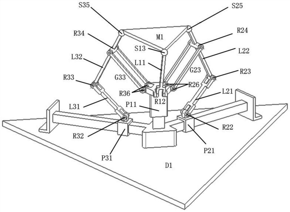
[0022] The structure of a three-degree-of-freedom heavy-duty robot mechanism in the embodiment is as follows: figure 1 As shown, it includes the frame (D1), the moving platform (M1), and the first branch, the second branch and the third branch connected in parallel between the frame (D1) and the moving platform (M1), and the connecting first branch and the third branch, the coupling chain between the first branch and the third branch; the axis of rotation of the first branch, the second branch and the third branch are parallel to each other; the axis of the moving axis and the axis of the rotation are perpendicular to each other; ) is connected to the frame (D1) through the first branch, the second branch and the third branch; the first rotating pair (R12) in the first branch is fixedly connected to the first moving pair (P11), and the first ...


PUM


Abstract

The invention discloses a two-rotation and one-movement asymmetrical coupling mechanism and belongs to the field of robot mechanisms. The mechanism comprises a machine frame, a movable platform, a first branch, a second branch, a third branch and coupling rod sets, wherein the first branch, the second branch and the third branch are used for connecting the movable platform with the machine frame; the coupling rod sets are connected between the first branch and the second branch as well as between the first branch and the third branch; each branch is composed of a prismatic, a rotation pair and a spherical pair; the P pair is vertically arranged on a base; and the axis of the R pair is perpendicular to the axis of the P pair. The second branch and the third branch are of the same structure. The second branch is composed of a prismatic, two rotation pairs and a spherical pair, wherein the axes of the R pairs are parallel and are perpendicular to the axis of the P pair. The second branch and the third branch are horizontally arranged, and the axis of the second branch and the axis of the third branch are distributed by 120 degrees. The first branch is connected with the second branch and the third branch through coupling rods with R pairs. Thus, the stability and the bearing capacity of the whole coupling mechanism can be improved to a certain extent.

Description

technical field [0001] The invention belongs to the field of robot mechanics, in particular to a three-degree-of-freedom mechanism with two rotations and one movement characteristics. Background technique [0002] Configuration synthesis has always been a research hotspot in mechanism science, and is the root of mechanical innovation. The development of institutions has gone through a process ranging from simple to complex. In some high-strength, heavy-duty workplaces that require industrial robotic arms to replace human labor, it is often required that the actuators of the robotic arms have high strength, simple structure, low cost, and convenient maintenance. control needs. Both series mechanism and parallel mechanism have their own characteristics and application occasions, but the advantages of one of them are the disadvantages of the other. For example, the series mechanism has relatively low stiffness and low bearing capacity, while the parallel mechanism has a smal...

Claims


Application Information

Patent Timeline
Patent Type & Authority Patents(China)
IPC IPC(8): B25J9/00
CPCB25J9/0033
Inventor 张家诚刘婧芳
Owner BEIJING UNIV OF TECH
Learn More