
Automobile hub with balance block

A technology for automobile wheels and balance weights, which is applied in the direction of wheel weights, coatings, anti-corrosion coatings, etc., and can solve problems such as increasing the abnormal wear and tear of automobile tires and suspension systems, driving safety cannot be guaranteed, and increasing the difficulty of automobile control. , to achieve the effect of simple structure, improved service life and safe use

Inactive Publication Date: 2017-12-26
陈伟景
View PDF6 Cites 3 Cited by
  • Summary
  • Abstract
  • Description
  • Claims
  • Application Information

AI Technical Summary

Problems solved by technology

[0002] The balance weight, also known as the tire balance weight, is a counterweight component installed on the wheel of the vehicle. The function of the balance weight is to keep the wheel in dynamic balance under high-speed rotation. If the quality of the car wheel is uneven, during this high-speed driving process , will not only affect the comfort of the car, but also increase the abnormal wear of the car tires and suspension system, increase the difficulty of controlling the car during driving, and lead to unsafe driving. In order to avoid this situation, the wheels should be installed before The dynamic balance test must be carried out by the special equipment - wheel dynamic balance machine. Appropriate counterweight is added to the small part of the wheel to keep the dynamic balance of the wheel under high-speed rotation. This kind of counterweight is the wheel balance block. The existing balance The weight stands directly on the steel ring, and it is easy to fall off after long-term use, driving safety cannot be guaranteed, and once the balance weight is removed, it must be replaced, wasting resources

Method used


Image

  • Automobile hub with balance block
  • Automobile hub with balance block

Examples


Embodiment Construction

[0018] The following will clearly and completely describe the technical solutions in the embodiments of the present invention with reference to the accompanying drawings in the embodiments of the present invention. Obviously, the described embodiments are only some, not all, embodiments of the present invention. Based on the embodiments of the present invention, all other embodiments obtained by persons of ordinary skill in the art without making creative efforts belong to the protection scope of the present invention.

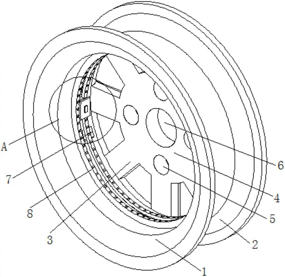
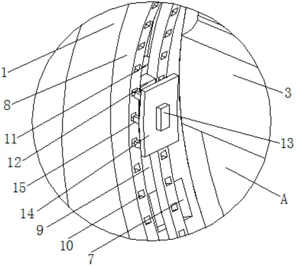
[0019] see Figure 1-2 , the present invention provides a technical solution: a car wheel hub with a self-contained balance weight, including a steel rim 1, the outer surface of the steel rim 1 is provided with a bead seat 2, which is convenient for tire installation, and the left end of the outer surface of the steel rim 1 The middle part is provided with a valve hole 7, which is convenient for the installation of the tire valve core. The rear end of the inne...


PUM


Abstract

The invention discloses an automobile hub with a balance block. The hub comprises a steel ring, a tire bead base is arranged on the outer side surface of the steel ring, and a valve hole is formed in the middle of the left end of the outer side surface of the steel ring; wheel arms are arranged at the back end of the inner side surface of the steel ring, a fixing plate is arranged at the ends, away from the steel ring, of the wheel arms, and a center hole is formed in the middle of the side surface of the fixing plate; mounting holes which are evenly distributed are formed in the edge of the side surface of the fixing plate, the four mounting holes are evenly formed in the side surface of the fixing plate, and an annular plate is arranged on the middle of the inner side surface of the steel ring; an annular sliding groove is formed in the middle of the side surface of the annular plate, the balance block is arranged in the annular sliding groove, and the balance block is connected with the annular sliding in a sliding mode. The automobile hub with the balance block is simple in structure, the balance block can be adjusted and conveniently fixed, the service life of the balance block can be effectively prolonged, resource waste is reduced, meanwhile, the driving safety is improved, and the automobile hub is used safely and is high in practicability.

Description

technical field [0001] The invention relates to the technical field of automobile wheels, in particular to an automobile wheel with its own balance weight. Background technique [0002] The balance weight, also known as the tire balance weight, is a counterweight component installed on the wheel of the vehicle. The function of the balance weight is to keep the wheel in dynamic balance under high-speed rotation. If the quality of the car wheel is uneven, during this high-speed driving process , will not only affect the comfort of the car, but also increase the abnormal wear of the car tires and suspension system, increase the difficulty of controlling the car during driving, and lead to unsafe driving. In order to avoid this situation, the wheels should be installed before installation The dynamic balance test must be carried out by a special equipment - a wheel dynamic balance machine. Appropriate counterweights are added to the small part of the wheel to keep the wheels in ...

Claims


Application Information

Patent Timeline
Patent Type & Authority Applications(China)
IPC IPC(8): B60B15/28C09D175/02C09D133/02C09D5/08C09D7/12
CPCB60B15/28C08K2003/2227C08K2003/2241C08K2201/011C08L2205/035C09D5/08C09D175/02C08L33/02C08L1/284C08K13/02C08K3/22C08K3/34C08K5/42C08K3/04
Inventor 陈伟景
Owner 陈伟景
Learn More