Rearview mirror wiper for overall wiping and rearview mirror thereof

A rear-view mirror and wiper technology, which is applied to vehicle cleaning, vehicle maintenance, optical observation devices, etc., can solve the problems of blurred rear-view mirrors, poor controllability of wipers, and sweeping of rear-view mirrors, so as to improve the cleaning effect, Avoid re-blur effects

Pending Publication Date: 2017-12-26
马胜利
View PDF11 Cites 5 Cited by
  • Summary
  • Abstract
  • Description
  • Claims
  • Application Information

AI Technical Summary

Problems solved by technology

[0006] For example, the rearview mirror wiper uses a worm to drive the gear and the connecting piece to rotate, so that the wiper swings and removes the accumulated water in the rearview mirror. The basic principle is: start the switch, and after the motor is powered on, it drives the worm at the output end of the motor to rotate, and the worm drives the rotating gear Rotate, and then drive the wiper shaft to rotate through a series of connecting rods, and finally the wiper shaft drives the wiper blade of the rearview mirror to swing to achieve the purpose of removing the rain on the mirror surface. This type of wiper device with more transmission mechanisms is adopted , requires a series of connecting rods and gears to be engaged to achieve rotation. After a long period of use, it is necessary to lubricate, replace or maintain the corresponding mechanical components. So many mechanical transmission components are difficult to achieve thorough maintenance. At the same time, these The mechanical components of the mechanical transmission rearview mirror wiper

Method used


Image

  • Rearview mirror wiper for overall wiping and rearview mirror thereof
  • Rearview mirror wiper for overall wiping and rearview mirror thereof
  • Rearview mirror wiper for overall wiping and rearview mirror thereof

Examples


Embodiment 1

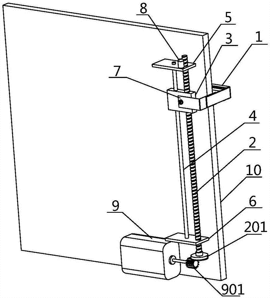
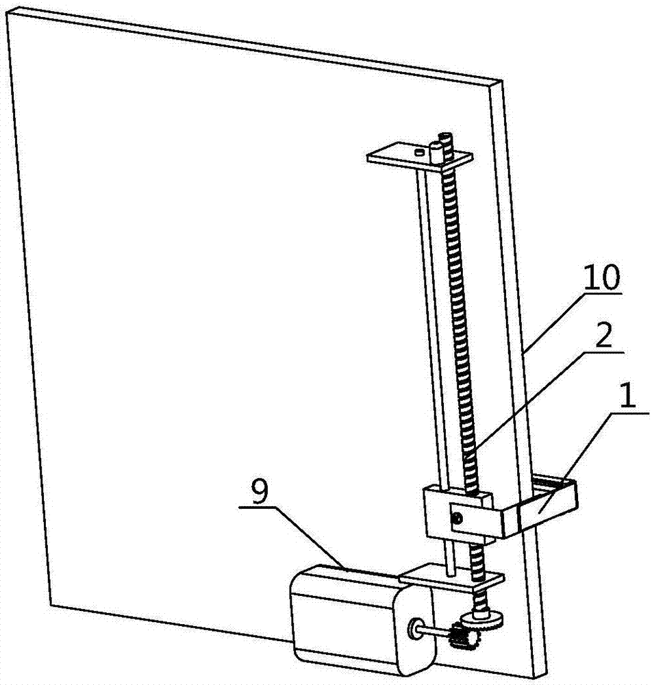
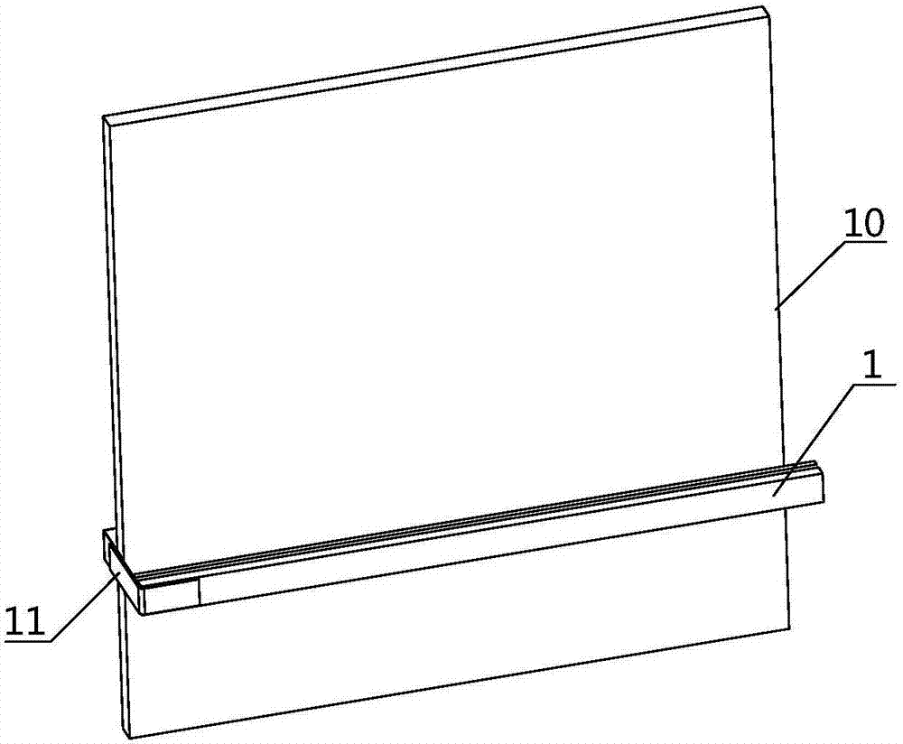
[0033] Such as Figure 1-3 As shown, the rearview mirror wiper convenient for comprehensive sweeping according to Embodiment 1 of the present invention, the rearview mirror wiper includes an elastic wiper portion 1 arranged on the outer surface of the mirror panel 10 and used for comprehensive sweeping. 10 is the sliding mechanism used to make the wiper unit 1 move up and down on the back, and the driving device used to drive the sliding mechanism.

[0034] First, further analysis of the sliding mechanism set above:

[0035] Described sliding mechanism has slide rail 4; Because can according to the demand of the shape of mirror panel 10 and the brushing mode, slide rail 4 is vertically set from top to bottom on mirror panel 10 backside and this slide rail 4 upper and lower ends pass through respectively The upper position positioning plate 5 and the lower position positioning plate 6 are fixed on the back of the mirror panel 10 or in the parts cavity on the inner side of the ...

Embodiment 2

[0044] Such as Figure 1-3 As shown, the rearview mirror wiper convenient for comprehensive sweeping described in Embodiment 2 of the present invention includes a wiper portion 1 arranged on the outer surface of the mirror panel 10 and used for comprehensive sweeping, and arranged on the back of the mirror panel 10 for use. The wiper unit 1 is a sliding mechanism for moving up and down, and a driving device for driving the sliding mechanism.

[0045] First, further analysis of the sliding mechanism set above:

[0046] The back side of the mirror panel 10 has a housing and the inside of the housing has a component cavity, and a sliding mechanism with a slide rail 4 is installed in the component cavity; a slide block 3 is sleeved on the slide rail 4, and the outer surface of the slide block 3 is Connect the connecting guide plate 7, because the slider 3 and the wiper portion 1 are separated by the mirror plate 10, therefore, the connecting guide plate 7 is an L-shaped structure...

Embodiment 3

[0050] Such as Figure 1-3 As shown, a rearview mirror convenient for comprehensive sweeping described in Embodiment 3 of the present invention includes a mirror panel 10 of a rectangular structure and a housing for fixing the mirror surface. The mirror surface of the rectangular structure is provided with a wiper portion 1, and the mirror panel 10 A sliding mechanism for swiping the wiper unit 1 up and down is provided between the back surface and the casing, and a driving device for driving the sliding mechanism is provided below the sliding mechanism.

[0051] First, further analysis of the sliding mechanism set above:

[0052] The sliding mechanism is arranged in the housing on the back of the mirror panel 10, so that there is no need to additionally configure a wiper drive box to occupy the space outside the car body, which will neither affect the appearance of the car body nor hinder cleaning and maintenance;

[0053] Owing to can according to the demand of the shape of...


PUM


Abstract

The invention relates to a rearview mirror wiper for overall wiping and a rearview mirror thereof. The rearview mirror wiper comprises a wiper portion which is arranged on the outer surface of a mirror plate and used for overall wiping, a sliding mechanism which is arranged on the back surface of the mirror plate, enables the wiper portion to carry out up-down wiping and is provided with a sliding rail, and a driving device used for driving the sliding mechanism. The upper end and lower end of the sliding rail have limiting points and are provided with wiper position sensors which are used for sensing the up-down movement position of a sliding block. The driving device comprises a stepping motor and a toothed driving wheel arranged at the output end of the stepping motor. The rearview mirror wiper for overall wiping and the rearview mirror thereof have the beneficial effects that the structure can fill in the blank in the prior art and can overall wipe rectangular rearview mirrors like oblong or square rearview mirrors, especially for rearview mirrors of buses, trucks and the like; vertical worms are used for driving wiper bars for parallel wiping, so that the cleaning effect is improved and no dead corners are left; and the wiper structure does not affect position adjustment of the rearview mirror.

Description

technical field [0001] The invention relates to the technical field of windshield wipers for vehicles, in particular to a rearview mirror wiper and a rearview mirror which are convenient for comprehensive sweeping. Background technique [0002] Traditional wiper generally refers to a tool for simple cleaning on the front glass of a motor vehicle to prevent rainwater and other dirt from affecting the line of sight. The wiper or wiper is an essential part of the car. It is used to turn the water droplets on the car glass into a uniform water film. The uniform water film will not cause light refraction, so that the driver can get a clear vision and improve driving. Safety. At present, traditional wipers are generally installed on the surface of the front windshield or the rear windshield. They only clean up the rainwater in these two areas, and cannot clean up other important parts of the vehicle, such as the rearview mirrors on both sides of the vehicle. . [0003] When it i...

Claims


Application Information

Patent Timeline
IPC IPC(8): B60R1/06B60S1/60
CPCB60R1/0602B60S1/60
Inventor 马胜利
Owner 马胜利
Why Eureka
Try Eureka