
Automatic concrete pouring equipment for constructing bridge pile foundation

A concrete and pile foundation technology, which is applied in the field of automatic concrete pouring equipment for bridge pile foundation construction, can solve the problems of large resource consumption, long time consumption, complicated operation of pouring tools, etc., and achieve the effect of reducing labor intensity and improving strength

Inactive Publication Date: 2017-12-26
王辉
View PDF0 Cites 1 Cited by
  • Summary
  • Abstract
  • Description
  • Claims
  • Application Information

AI Technical Summary

Problems solved by technology

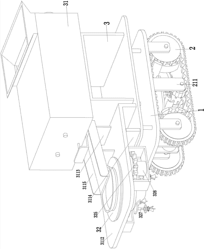
[0003] In order to solve the above problems, the present invention provides a concrete pouring equipment for the construction of bridge pile foundations, which can solve the need to use existing concrete mixer trucks to transport concrete during the construction of pile foundations in existing construction projects. The pile foundation pouring tool is used to fix the pile foundation. The road surface for building the pile foundation is complicated, especially in the rainy season when the ground is muddy. The existing concrete mixer trucks consume a lot of resources to transport the concrete pouring pile foundation. It is complicated to manually move the pouring tool to the working position with the help of the existing lifting mobile equipment. It takes a long time to manually control the stability of the pouring tool during work. In the process of concrete pouring, due to the heavy weight of concrete, manual control of pouring tools is prone to accidents and poses a threat to the safety of workers. It can realize the function of automatic pouring of pile foundation concrete, and automatically transport concrete, which can move stably on complex roads. There is no need to manually control the perfusion tool, there is no potential safety hazard, and it has the advantages of saving resources, low labor intensity, short time consumption and high work efficiency

Method used


Image

  • Automatic concrete pouring equipment for constructing bridge pile foundation
  • Automatic concrete pouring equipment for constructing bridge pile foundation
  • Automatic concrete pouring equipment for constructing bridge pile foundation

Examples


Embodiment Construction

[0021] In order to make the technical means, creative features, goals and effects achieved by the present invention easy to understand, the present invention will be further described below in conjunction with specific illustrations.

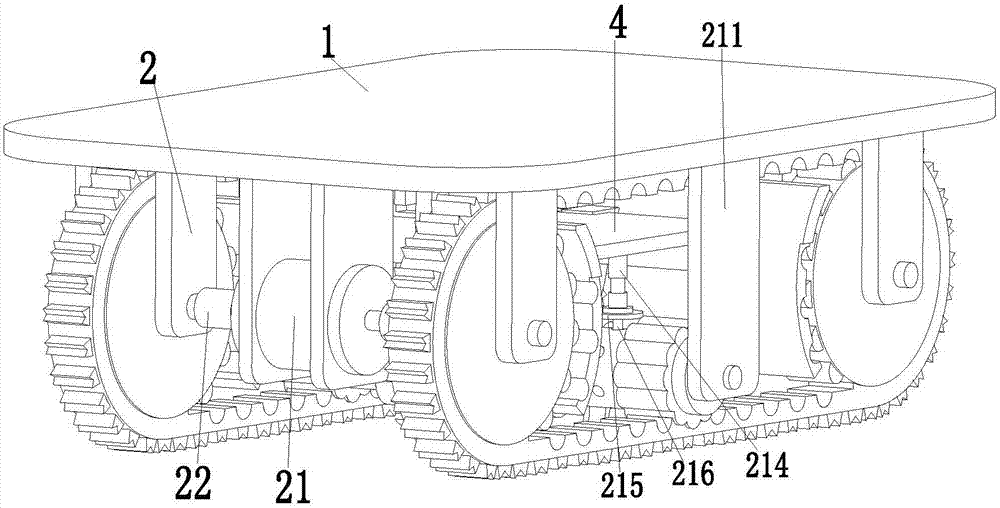
[0022] Such as Figure 1 to Figure 4 Shown, a kind of concrete pouring equipment for bridge pile foundation construction, comprises base plate 1, and the lower end of base plate 1 is equipped with moving device 2, and the upper end of base plate 1 is equipped with pouring device 3, and moving device 2 can drive the present invention on complicated road surface Moving smoothly, the pouring device 3 can perform automatic pile foundation pouring operations, and the moving device 2 and the pouring device 3 cooperate with each other to complete the process of pile foundation concrete automatic pouring.

[0023] The moving device 2 includes a bidirectional drive motor 21 installed on the front side of the lower end of the base plate 1 through a motor ...


PUM


Abstract

The invention relates to an automatic concrete pouring equipment for bridge pile foundation construction, which comprises a base plate, a moving device is installed at the lower end of the base plate, and a pouring device is installed at the upper end of the base plate. The present invention can solve the problems existing in the pile foundation construction process of existing construction projects that concrete needs to be transported by means of the existing concrete mixer truck, the existing pile foundation pouring tools need to be manually fixed, the road surface for pile foundation construction is complicated, and there is much rain. season, the ground is muddy, and the existing concrete mixer trucks have no corresponding protective measures on the muddy road surface, and are easy to sink into the muddy road surface, and the use of existing concrete mixer trucks to transport concrete pouring pile foundations consumes a lot of resources, and artificial Heavy mobile equipment moves the pouring tool to the working position, and the operation is complex. Manual control of the pouring tool is prone to accidents and poses a threat to the safety of workers. It can realize the function of automatic pouring of pile foundation concrete.

Description

technical field [0001] The invention relates to the technical field of bridge construction engineering equipment, in particular to an automatic pouring equipment for concrete used in bridge pile foundation construction. Background technique [0002] The pile foundation is composed of a pile foundation and a cap connected to the pile top. If the pile body is completely buried in the soil and the bottom of the cap is in contact with the soil, it is called a low cap pile foundation; if the upper part of the pile body is exposed to the ground and the bottom of the cap is above the ground, it is called a high cap pile foundation. Construction pile foundations are usually low cap pile foundations. It is widely used in high-rise buildings, bridges, high-speed rail and other projects. To build pile foundations, it is necessary to drill holes in the construction site, then install the reinforced mold bundled with steel bars or steel pipes into the existing installation holes, and fi...

Claims


Application Information

Patent Timeline
Patent Type & Authority Applications(China)
IPC IPC(8): E02D15/04B28C5/08B28C5/14
CPCE02D15/04B28C5/0806B28C5/0856B28C5/14E02D2250/0023
Inventor 王辉
Owner 王辉
Learn More