Antenna with radiation pattern reconfigurable

A technology of radiation direction and pattern, which is applied to antennas, antenna arrays, specific array feeding systems, etc., and can solve problems such as ineffective coverage and fixed coverage of transmitting antennas.

Pending Publication Date: 2017-12-26
CHINA UNITED NETWORK COMM GRP CO LTD
View PDF13 Cites 17 Cited by
  • Summary
  • Abstract
  • Description
  • Claims
  • Application Information

AI Technical Summary

Problems solved by technology

[0004] However, at present, the layout of high-rise buildings in cities and residential buildings in residential areas is complex. If the radiation pattern parameter

Method used


Image

  • Antenna with radiation pattern reconfigurable
  • Antenna with radiation pattern reconfigurable
  • Antenna with radiation pattern reconfigurable

Examples


Embodiment Construction

[0044] Here, exemplary embodiments will be described in detail, and examples thereof are shown in the accompanying drawings. When the following description refers to the drawings, unless otherwise indicated, the same numbers in different drawings indicate the same or similar elements. The implementation manners described in the following exemplary embodiments do not represent all implementation manners consistent with the present disclosure. Rather, they are only examples of antennas consistent with some aspects of the present disclosure as detailed in the appended claims.

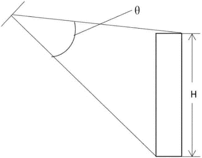
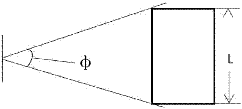
[0045] figure 1 This is a scene diagram of a vertical coverage of a building by an antenna according to an embodiment of the present invention. figure 2 This is a scene diagram of the horizontal coverage of a building by an antenna provided in an embodiment of the present invention. Such as figure 1 As shown, H represents the height of the building, and θ represents the vertical coverage angle of the antenn...


PUM


Abstract

The embodiment of the invention provides an antenna with the radiation pattern reconfigurable. The antenna with the radiation pattern reconfigurable comprises a Butler matrix module, a phase shift feed network module and an antenna oscillator array; the Butler matrix module is electrically connected with the phase shift feed network module, and the Butler matrix module or the phase shift feed network module is electrically connected with the antenna oscillator array, wherein the Butler matrix module is used for outputting multipath feed signals; the phase shift feed network module is used for regulating the phase of each path of feed signals in the multipath feed signals; the multipath feed signals with the phase adjustable feed a plurality of antenna oscillator units, the beam width of the antenna radiation pattern varies with the phase of the multipath feed signals, and the inclined angle of the antenna radiation pattern varies with the phase of the multipath feed signals. By means of the antenna with the radiation pattern reconfigurable, the antenna can adapt to a building with a complicated layout, and the building can be effectively covered.

Description

Technical field [0001] The embodiment of the present invention relates to the field of communication technology, and in particular to an antenna with a reconfigurable radiation pattern. Background technique [0002] With the development of communication technology, the transmitting antenna is an indispensable part of the communication equipment, and the transmitting antenna plays the function of receiving and sending signals. [0003] In the prior art, the radiation pattern parameters of the transmitting antenna are fixed. For example, the horizontal half-power angle of the directional antenna is about 65 degrees, and the vertical half-power angle is about 10 degrees. [0004] However, the current layout of urban high-rise buildings and residential buildings in residential areas is complicated. If the radiation pattern parameters of the transmitting antenna are fixed, the coverage of the transmitting antenna is relatively fixed, and the complex layout cannot be effectively covered. ...

Claims


Application Information

Patent Timeline
IPC IPC(8): H01Q3/30H01Q21/00
CPCH01Q3/30H01Q21/0025
Inventor 冷俊沙甲戊苗玉斌杨福理刁振宇殷海云张进宋峻董惠敏谷俊江张国光褚旭韩佳霖
Owner CHINA UNITED NETWORK COMM GRP CO LTD
Why Eureka
Try Eureka