Automatic feeding and discharging punch

A technology of automatic loading and unloading and punching, which is applied in metal processing equipment, feeding devices, manufacturing tools, etc., can solve the problems of wasting manpower and increasing the operation risk of operators, and achieves improved work efficiency, convenient automatic production, and high positioning accuracy. Effect

Active Publication Date: 2017-12-29
宁波臣力五金科技有限公司
View PDF7 Cites 18 Cited by
  • Summary
  • Abstract
  • Description
  • Claims
  • Application Information

AI Technical Summary

Problems solved by technology

This way of placing semi-finished products and removing stamped products not only wastes manpower, but also increases the operating risk of operators

Method used


Image

  • Automatic feeding and discharging punch
  • Automatic feeding and discharging punch
  • Automatic feeding and discharging punch

Examples


Embodiment Construction

[0044] The present invention will be described in further detail below in conjunction with the accompanying drawings.

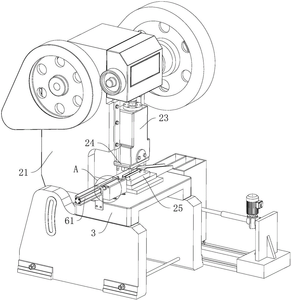
[0045] like image 3 and Figure 5 As shown, a punching machine for automatic loading and unloading includes a frame 21, a drive motor 22, a stamping slider 23 that is arranged on the frame 21 and is driven by the drive motor 22 to slide up and down, and a stamping slider 23 that is arranged below the stamping slider 23. workbench3. Wherein, the lower end surface of the stamping slider 23 is provided with a stamping upper die 24 , and the upper end surface of the workbench 3 is provided with a stamping lower die 25 opposite to the stamping upper die 24 .

[0046] like image 3 and Figure 4 As shown, the workbench 3 is provided with an installation through hole 31 through the upper and lower end faces of the workbench 3 on the left side of the stamping lower die 25, and an upper material box 4 installed in the installation through hole 31 and used for the...


PUM


Abstract

The invention discloses an automatic feeding and discharging punch. The problems that in the prior art, manpower is wasted for feeding and discharging of a punch, and potential safety hazards exist are solved. According to the technical scheme, the automatic feeding and discharging punch is characterized in that the automatic feeding and discharging punch comprises a workbench and a punching lower die, a feeding box is arranged on the part, on one side of the punching lower die, of the workbench, the upper end face of the feeding box is flush with the upper end face of the punching lower die, and the feeding box is provided with an elevating mechanism elevating a semi-finished fixing piece; the workbench is further provided with a pushing mechanism pushing the semi-finished fixing piece; the punching lower die is further provided with a first positioning column abutting against the end portion of a side plate of the semi-finished fixing piece in the punching process, and a collecting box for containing a television support fixing piece is arranged on the workbench part on the side, away from the pushing device, of the punching lower die; and according to the punch, semi-finished punched part feeding and television support fixing piece discharging can be achieved without manpower, the manpower is saved, and meanwhile operation risks of operators are reduced.

Description

technical field [0001] The invention relates to the technical field of mechanical processing, in particular to a punch press for automatic loading and unloading. Background technique [0002] Punching machine is a kind of stamping press, because compared with traditional mechanical processing, punching machine has the advantages of saving materials and energy, high efficiency, low technical requirements for operators, and the ability to process different products through molds. Therefore, punching machine being widely used. When bending and stamping sheet metal stamping parts, such as figure 1 As shown, a TV bracket fixture 1 includes a base plate 11 and two side plates 12 arranged on both sides of the base plate 11 and longer than the base plate 11. The two side plates 12 are perpendicular to the base plate 11, and the side plates 12 are formed by It is punched by a punch press. like figure 2 As shown, it is the semi-finished product 1' of the above-mentioned TV bracke...

Claims


Application Information

Patent Timeline
Patent Type & Authority Applications(China)
IPC IPC(8): B21D22/02B21D43/02B21D43/20B21D43/24
CPCB21D22/02B21D43/027B21D43/20B21D43/24
Inventor 周发登
Owner 宁波臣力五金科技有限公司
Why Eureka
Try Eureka