Electronic lock

An electronic lock and lock lever technology, applied in the field of electronic locks, can solve the problems of cumulative increase in transmission error of electronic locks, premature triggering of micro switches, poor control accuracy, etc., and achieves improved use performance, small size, simple and compact structure. Effect

Active Publication Date: 2017-12-29
浙江致威电子科技有限公司
View PDF8 Cites 3 Cited by
  • Summary
  • Abstract
  • Description
  • Claims
  • Application Information

AI Technical Summary

Problems solved by technology

[0006] Therefore, the technical problem to be solved by the present invention is to overcome the accumulative increase of the electronic lock transmission error in the prior art, and the micro switch is triggered before the ejector rod is locked in place, so that the locking movement of the ejector rod and the triggering of the micro switch The cooperation between them is not well controlled, and the control accuracy is poor, which leads to the problem that the micro switch triggers too early or too late

Method used


Image

  • Electronic lock
  • Electronic lock
  • Electronic lock

Examples


Embodiment 1

[0052] Below in conjunction with accompanying drawing this embodiment is described in detail:

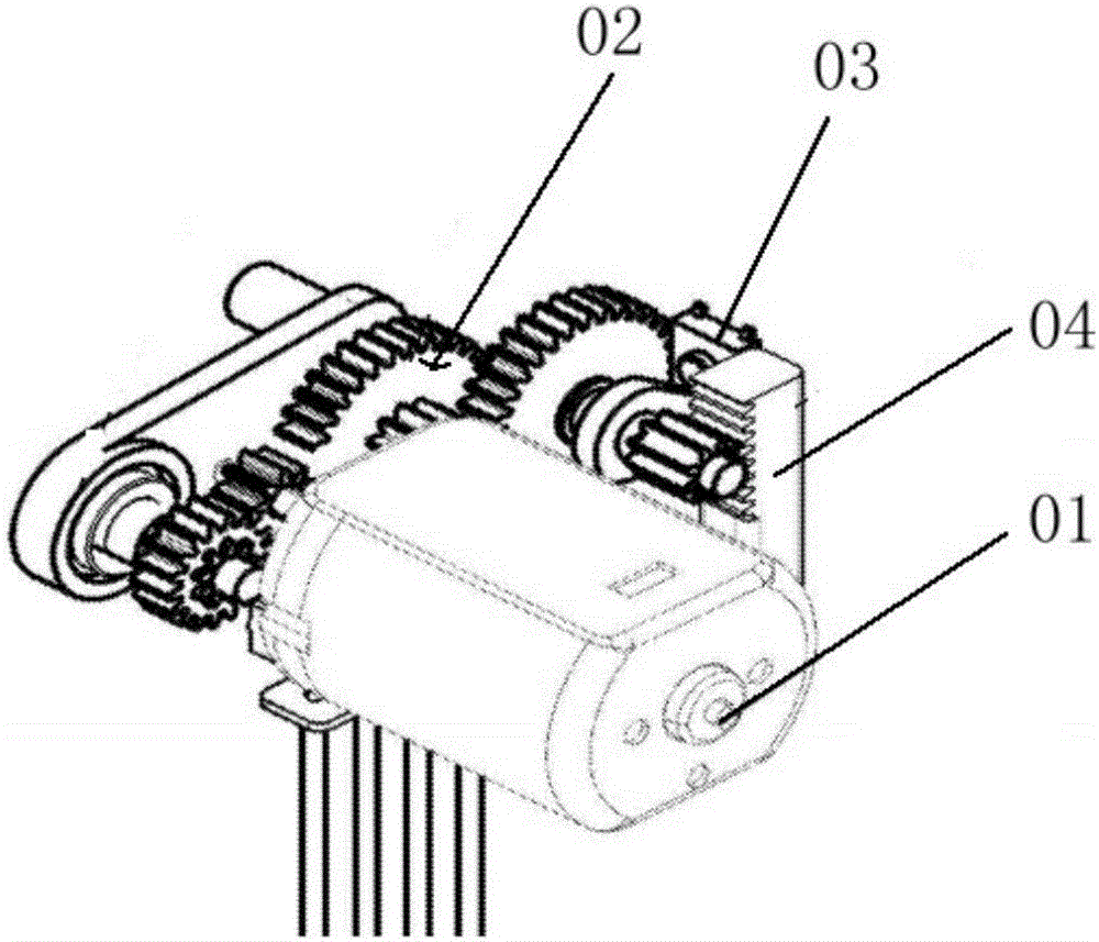
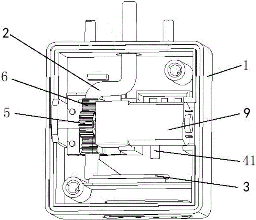
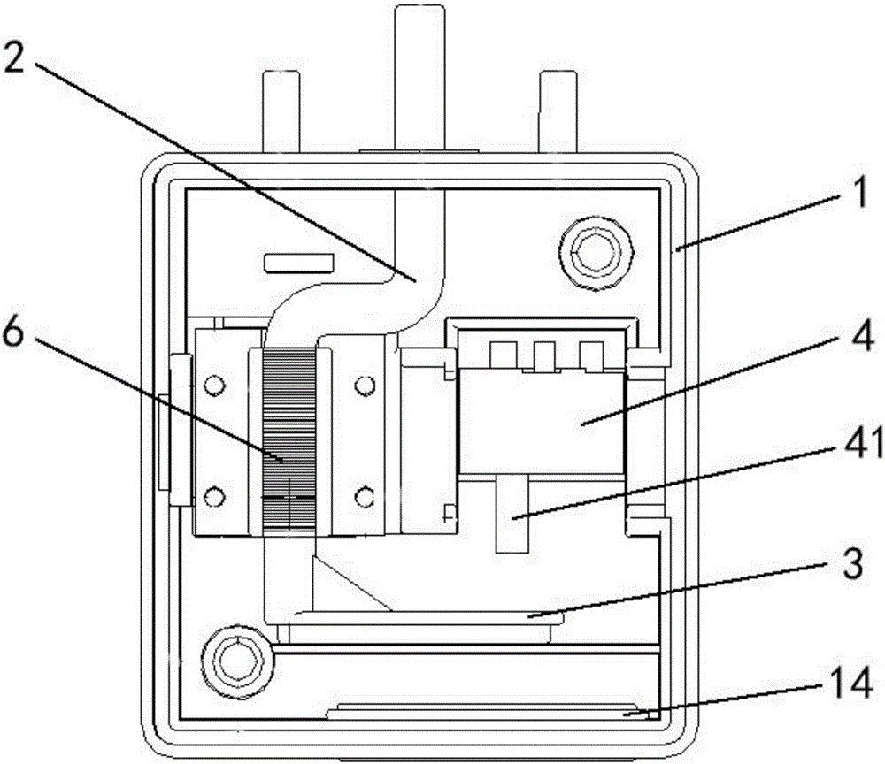
[0053] This example provides Figure 2-8 A kind of electronic lock shown, comprises: housing 1, and the driving device that is arranged in described housing, also comprises:

[0054] The signal triggering device 4 includes a signal triggering body and a trigger button 41. The signal triggering body opens and sends a locking indication signal when the trigger button 41 is pressed and pressed; when the trigger button 41 is not touched and pressed, Close and issue an unlock indication signal;

[0055] The locking structure 2 reciprocates under the driving of the driving device, and has a first state for locking the electronic lock, and a second state for unlocking the electronic lock;

[0056] The trigger structure 3 reciprocates under the drive of the driving device, and contacts and presses the trigger button 41 when the locking structure 2 is in the first state, and when the locki...


PUM


Abstract

The invention discloses an electronic lock. The electronic lock comprises a housing, as well as a driving device, a signal triggering device, a locking structure and a triggering structure which are arranged in the housing, wherein the signal triggering device is provided with a triggering button; the locking structure has a first state and a second state which can enable the electronic lock to be locked or unlocked; and the reciprocating direction of the triggering structure is consistent with that of the pressed or bounced triggering button. By adoption of the structural arrangement, the triggering structure can be in contact with and press the triggering button when the locking structure is in the first state, and can be separated from the triggering button when the locking structure is in the second state. According to the technical scheme, the electronic lock is simple and compact in structure, small in size and reliable in matched transmission, ensures the consistency and the synchronicity between the instantaneous triggering time of the signal triggering device and the corresponding locking/unlocking time of the electronic lock, is high in control accuracy and is safe and reliable, and the service performance of the electronic lock is improved.

Description

technical field [0001] The invention relates to the technical field of locks, in particular to an electronic lock. Background technique [0002] Traditional locks adopt a purely mechanical structure, which cannot realize intelligent control, and it is difficult to monitor and observe the status information of the lock. Today, with the rapid development of information technology, electronic locks, which are different from traditional mechanical locks, have emerged at the historic moment, which are safe and convenient. Features such as advanced technology and advanced technology are widely used in people's lives. [0003] At present, electronic locks on the market generally use motor-driven methods for unlocking and locking, such as figure 1 As shown, it includes a motor 01, a gear assembly 02, a micro switch 03 and a lock cylinder 04. The gear assembly is composed of several gears meshing with each other. The bump is used to trigger the micro switch, so that the micro switc...

Claims


Application Information

Patent Timeline
Patent Type & Authority Applications(China)
IPC IPC(8): E05B47/00E05B15/00
CPCE05B15/00E05B15/0013E05B47/0001E05B2047/002Y02T90/14
Inventor 赵顺荣陈寿强朱学锋
Owner 浙江致威电子科技有限公司
Why Eureka
Try Eureka