Controlling a vacuum system comprising a vacuum generator arrangement

A technology of vacuum generator and vacuum system, applied in the field of vacuum system

Active Publication Date: 2018-01-02
派亚博股份公司
View PDF13 Cites 3 Cited by
  • Summary
  • Abstract
  • Description
  • Claims
  • Application Information

AI Technical Summary

Problems solved by technology

[0008] Thus, a drawback is that the operator must apply a manually set threshold ES for any gripping tool at the station 低 and ES 高
Another drawback or problem is that the operator must be very skilled and experi

Method used


Image

  • Controlling a vacuum system comprising a vacuum generator arrangement
  • Controlling a vacuum system comprising a vacuum generator arrangement
  • Controlling a vacuum system comprising a vacuum generator arrangement

Examples


Embodiment Construction

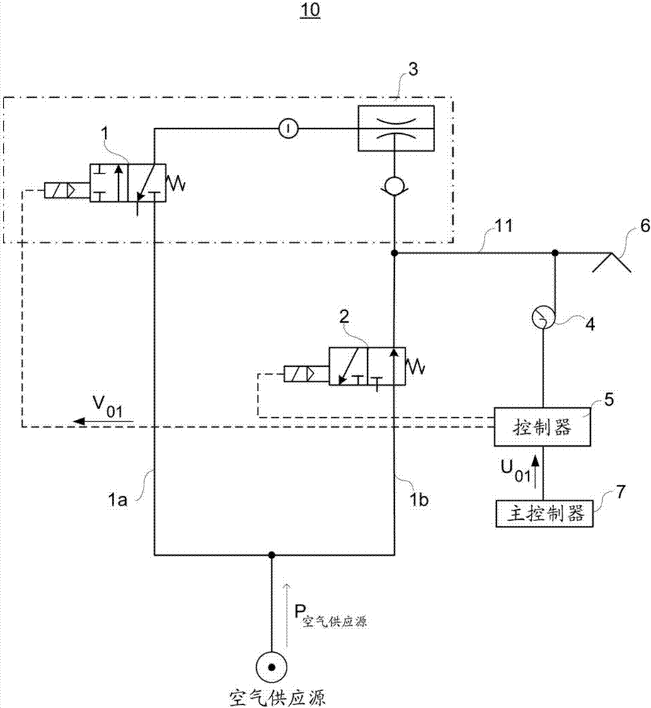
[0028] For a general description of an embodiment of a vacuum system 10 for transporting objects, reference is initially made to figure 1 .

[0029] Herein, "vacuum gripper" or "vacuum gripper tool" are used interchangeably, but both terms refer to the same kind of vacuum gripping mechanism, which may also include multiple vacuum grippers.

[0030] The vacuum system 10 comprises a vacuum generator 3 driven by a flow of compressed air via a first on / off valve 1 or other mechanism for controlling the flow of compressed air, wherein the vacuum generator 3 passes through a vacuum chamber which is part of the vacuum system 10 11 is arranged to be in fluid connection with one or more vacuum grippers 6 comprised in the vacuum system 10 so as to supply vacuum to the vacuum grippers 6 due to the flow of compressed air to the vacuum generator 3 . The vacuum system 10 comprises a second valve 2 arranged to supply compressed air into the vacuum system 10 . exist figure 1 , line P 空气供应源 ...


PUM


Abstract

The invention relates to controlling a vacuum system comprising a vacuum generator arrangement, and also relates to energy saving in vacuum systems by means of a method and a controller enabling to consider the fluctuation in system-pressure of a system by determining a maximum system-pressure S2H and a minimum system-pressure S2h for each working cycle W C based on a determined target system-pressure p n and a pre-set system-pressure p 0 for the current working cycle W Cn (n = 1, 2, 3, ...). The method is especially adapted to fluctuations in system-pressure level of a vacuum system comprising a vacuum gripper tool.

Description

technical field [0001] The present invention relates to a method of controlling a vacuum system comprising a vacuum generator device and a controller for a vacuum system comprising a vacuum generator device driven by compressed air in order to produce a vacuum suitable for suction cups or similar devices negative pressure. Background technique [0002] The present invention relates generally to material handling systems, and more particularly to a material handling system for controlling a vacuum generator assembly for a suction cup of a material handling system that engages an object and substantially The operation of the vacuum system is sealed with it. It is known to provide a material handling system comprising suction cups or the like adapted to move and lift and move an object such as a substantially flat object or panel or the like into a desired position. The suction cup is movable to engage the object, and the vacuum generator device can be actuated to create a va...

Claims


Application Information

Patent Timeline
IPC IPC(8): B65G47/91F04F5/52
CPCF04F5/20F04F5/52B66C1/0268G01L21/00G01M3/184G01M3/2815G01M3/2876G01M3/3263G01N1/14G05D16/2066
Inventor 古斯塔夫·威格任彼得·恩格堡
Owner 派亚博股份公司
Why Eureka
Try Eureka