
Elevator system

A kind of equipment and elevator technology, which is applied to elevators, elevators, transportation and packaging in buildings, etc., can solve the problems of preventing lateral derailment, and achieve the effects of reliable cost, improved tensile performance, and low cost

Inactive Publication Date: 2018-01-02
INVENTIO AG
View PDF5 Cites 0 Cited by
  • Summary
  • Abstract
  • Description
  • Claims
  • Application Information

AI Technical Summary

Problems solved by technology

[0004] But it has been shown that measures such as lateral edges cannot prevent lateral derailment in all cases

Method used


Image

  • Elevator system
  • Elevator system
  • Elevator system

Examples


Embodiment Construction

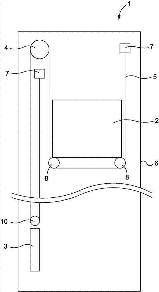
[0027] exist figure 1 An example embodiment of an elevator installation according to the prior art is shown in . The elevator system 1 comprises: a car 2 , a counterweight 3 , a drive 4 and a belt-shaped carrier 5 . Here, a belt-shaped carrier 5 is fastened in the elevator installation 1 by means of a first carrier fixture 7 and is guided past the counterweight deflection rollers 10 , past the drive pulley of the drive 4 , past the two car deflection rollers 8 and is fastened again in the elevator system 1 by means of the second support mechanism fastening 7 .

[0028] In the present exemplary embodiment, the elevator installation 1 is arranged in a shaft 6 . In an alternative embodiment, not shown, the elevator installation is not arranged in the shaft, but instead is fastened, for example, to the outer wall of the building.

[0029] figure 1 The elevator installation 1 of the example in includes a counterweight 3 . In an alternative embodiment not shown, the elevator in...


PUM


Abstract

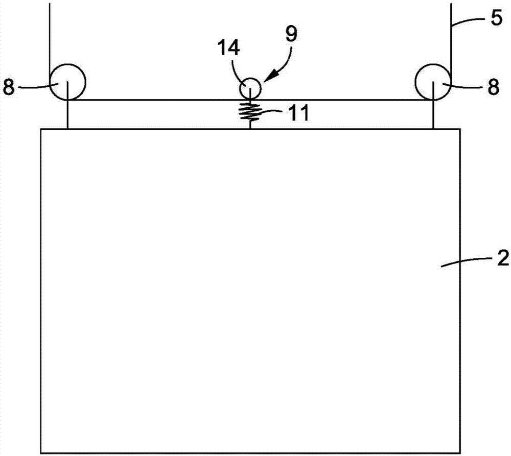
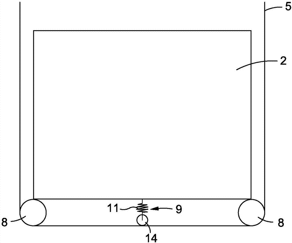
In an elevator system, a belt-type suspension means is guided over a driving pulley of a drive unit and over two deflection rolls on an elevator car. Between the two deflection rolls, the belt-type suspension means is additionally guided over a tensioning element which applies a force to the belt-type suspension means. The tensioning element is movably arranged such that the belt-type suspension means is displaced by the tensioning element when the tension diminishes and is thereby tensioned again.

Description

technical field [0001] The invention relates to an elevator installation with a tensioning device. Background technique [0002] In elevator installations, steel cables are conventionally used as support means for supporting and / or driving the elevator car. According to a further development of this steel cable, a belt-shaped carrier is also used, which has a tension carrier and a sheath arranged around the tension carrier. Such a belt-like carrier is guided in the elevator system like a conventional steel cable around the drive pulley and deflection rollers. In contrast to the steel cables, the belt-shaped support means are not guided in channels in the deflection rollers or drive wheels, but the belt-like support means lie flat on the deflection rollers or drive wheels. [0003] As a result, the belt-like support means are less well guided laterally on the deflection rollers or drive wheels than conventional steel cables. As a result, it can happen that the belt-like ca...

Claims


Application Information

Patent Timeline
IPC IPC(8): B66B7/10B66B7/06B66B11/08
CPCB66B11/0226
Inventor 阿布希沙克·韦勒卡尔沙欣·古里
Owner INVENTIO AG
Learn More