Eureka AIR delivers breakthrough ideas for toughest innovation challenges, trusted by R&D personnel around the world.

Control device for supercharging system

一种控制装置、增压系统的技术,应用在电气控制、发动机控制、机器/发动机等方向,能够解决设备破损等问题

Inactive Publication Date: 2018-01-02
MITSUBISHI HEAVY IND ENGINE & TURBOCHARGER LTD
View PDF10 Cites 3 Cited by
  • Summary
  • Abstract
  • Description
  • Claims
  • Application Information

AI Technical Summary

Problems solved by technology

In addition, if the surge state occurs frequently, it may cause damage to the equipment

Method used


Image

  • Control device for supercharging system
  • Control device for supercharging system
  • Control device for supercharging system

Examples


no. 1 approach

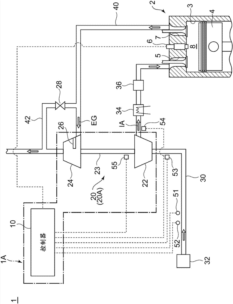
[0055] figure 1 It is a diagram showing the overall configuration of a supercharging system to which a supercharging system control device according to an embodiment of the present invention is applied. A supercharging system control device 1A according to an embodiment of the present invention is a supercharging system control device 1A for supplying compressed intake air IA to an engine 2, such as figure 1 As shown, there are: a supercharger 20 including a compressor 22 that compresses intake air IA supplied to the engine 2 , and a controller 10 that controls a control device that affects the operation of the compressor 22 .

[0056] In the illustrated embodiment, the supercharger 20 is constituted by a turbocharger 20A that rotates a compressor 22 by a turbine 24 that is rotated by exhaust gas EG discharged from the engine 2 .

[0057] exist figure 1 In the supercharging system 1 shown, the air (intake air) introduced into the intake line 30 via the air cleaner 32 flows i...

no. 2 approach

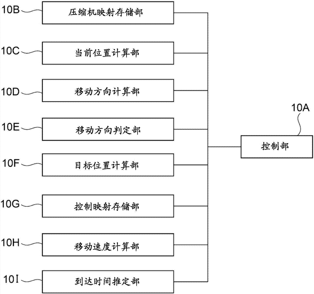
[0088] In several embodiments, such as figure 2 As shown, the controller 10 further includes a movement speed calculation unit 10H. The moving speed calculation unit 10H is a part of the controller 10 that realizes the function of calculating the moving speed of the operating point 61 based on the change amount per unit time of the current position of the operating point 61 calculated by the current position calculating unit 10C.

[0089] Moreover, as described later Figure 7 , 8 As described in , the control unit 10A is configured based on the current position of the operating point 61 calculated by the current position calculating unit 10C, the moving direction of the operating point 61 calculated by the moving direction calculating unit 10D, and the moving direction calculated by the moving speed calculating unit 10H. The calculated movement speed of the operating point 61 is used to control the control devices 6, 26, 28 and the like.

[0090] According to such an embo...

no. 3 approach

[0106] In several embodiments, as described below Figure 10-11 As described in , when the arrival time tb of the operating point 61 from the current position to the target position is shorter than the second predetermined time td, the control unit 10A controls the control devices 6, 26, 28, etc. so that The operating point 61 is made to reach the target position earlier than the second predetermined time td.

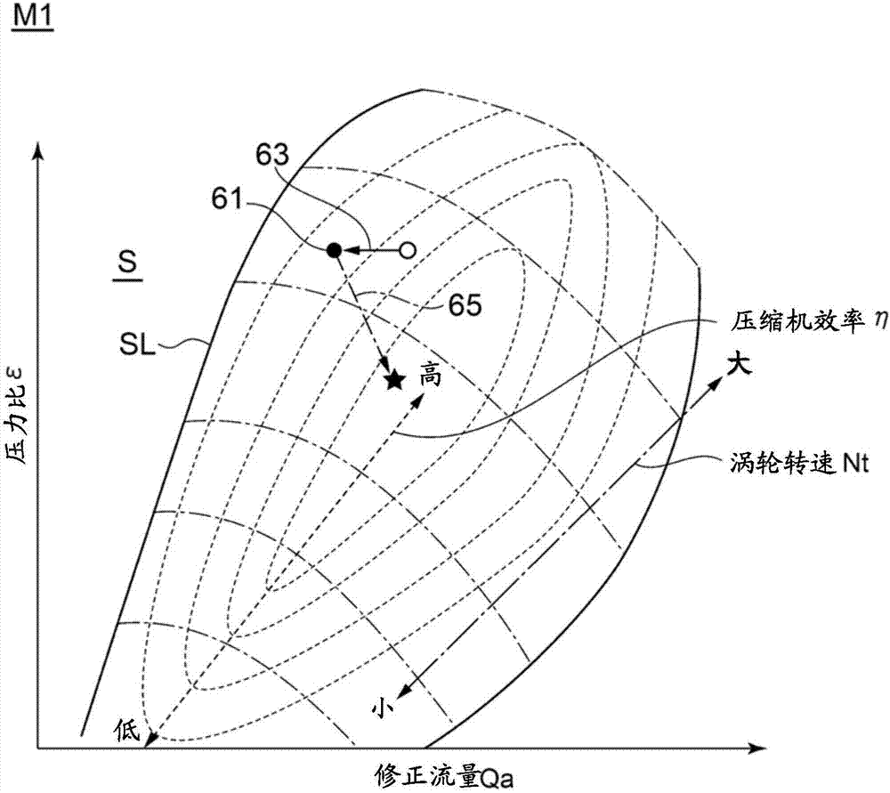
[0107] According to such an embodiment, when the arrival time of the operating point 61 from the current position to the target position is shorter than the second predetermined time td, the compressor 22 is controlled so that the operating point 61 is shorter than the second predetermined time td. Arrive at the target location ahead of schedule. The target position is, for example, a position on the compressor map M1 where the compressor efficiency η is higher than a predetermined efficiency (for example, a position where the compressor efficiency η is 75% or more). ...


PUM


Abstract

A control device for a supercharging system for supplying compressed intake air to an engine, is equipped with: a supercharger containing a compressor that compresses the intake air supplied to the engine; and a controller that controls control devices affecting the operation of the compressor. The controller includes: a compressor map storage unit storing a compressor map indicating the relationship between the intake air volumetric flow rate and the pressure ratio in the compressor and the compressor rotational frequency; a current position calculation unit that calculates, for each prescribed period, the current position of the operation point of the compressor in the compressor map; a movement direction calculation unit that calculates the direction of movement of the operation point in the compressor map, on the basis of the current position of the operation point as calculated by the current position calculation unit; and a control unit that controls the control devices on the basis of the current position of the operation point as calculated by the current position calculation unit, and the movement direction of the operation point as calculated by the movement direction calculation unit.

Description

technical field [0001] The present disclosure relates to a control device for a boost system for supplying compressed intake air to an engine. Background technique [0002] A method of compressing intake air with a supercharger and supplying the compressed intake air to an engine (supercharging) is known as a technique for increasing the output of an engine, and is widely used in various engines. The supercharger sometimes temporarily enters an abnormal operating state called surge when the operating state of the engine changes suddenly. If the supercharger goes into surge, it can no longer compress the intake air. In addition, if the surge state occurs frequently, it may cause damage to the equipment. Therefore, it is necessary to properly control the supercharger to avoid the supercharger from entering a surge state. [0003] In the past, as a technology for controlling the supercharger, the following control is usually performed: the intake air flow rate, rotation spee...

Claims


Application Information

Patent Timeline
Patent Type & Authority Applications(China)
IPC IPC(8): F02D23/02F02B37/12F02D23/00F02D45/00
CPCF02D45/00F02D23/00F02D23/02F02B2037/125F02D41/1406F02B2037/122F02B37/24F02B37/18F02B37/22F02D41/0007F02D41/3005Y02T10/12
Inventor 高桥知大池田孝寺门贵芳森直之V.吉瓦里亚维杰
Owner MITSUBISHI HEAVY IND ENGINE & TURBOCHARGER LTD
Why Eureka
Eureka Blog
Learn More