Modified spring cushion for film frame shipper

A technology of conveyors and membrane racks, which is applied in the manufacture of electrical components, circuits, semiconductors/solid-state devices, etc., can solve problems such as damage to wafers, parts that can contact other wafers, racks 42 or conveyors, etc., to achieve enhanced jumping and jumping Effect of prevention and reduction of backlash

Active Publication Date: 2018-01-02
ENTEGRIS INC
View PDF5 Cites 2 Cited by
  • Summary
  • Abstract
  • Description
  • Claims
  • Application Information

AI Technical Summary

Problems solved by technology

When a film carrier becomes disengaged during an impact event, wafers on the disengaged film carrier can contact other wafers, racks 42, or parts of the conveyor, causing damage to the wafers

Method used


Image

  • Modified spring cushion for film frame shipper
  • Modified spring cushion for film frame shipper
  • Modified spring cushion for film frame shipper

Examples


Embodiment Construction

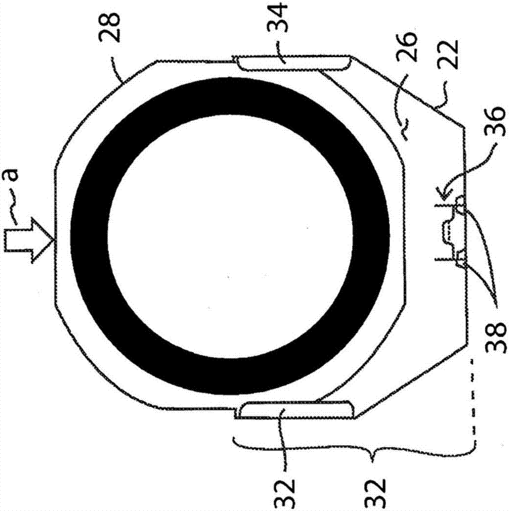
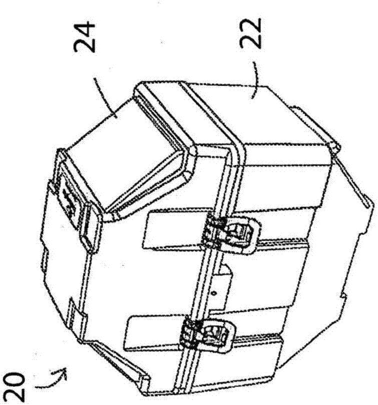
[0029] figure 1 Through 4 depict the frame conveyor 20 in an embodiment of the present invention. The film rack conveyor 20 includes a container 22 and a cover 24 forming a closure over the container portion to define an interior chamber 26 for storing a plurality of film racks 28 . The container 22 includes sides 32 that may include guides 34 ( FIG. 2 ) for guiding the membrane holder 28 into the container 22 . Spring rack pad 36 is coupled to at least one of container 22 and lid 24 . In one embodiment, the rack pad 36 is removably mounted to a grooved rail 38 on the container 22 or lid 24 . As shown, the film holder 28 is directed in a direction A into the interior chamber 26 of the container 22 and then the lid 24 is moved in the same direction A to couple with the container 22 .

[0030] refer to Figures 6 to 8 , depicts the form of the spring mount 36 in an embodiment of the invention. Spring mount 36 is specifically referred to as spring mount 36a ( Figure 6 ) a...


PUM


Abstract

A film frame shipper that provides enhanced prevention of the jumping of film frames within the film frame shipper. In addition, the structures that prevent jumping also augment alignment of the filmframes during loading into the shipper. Furthermore, in certain embodiments, these structures enable a closer tolerance fit between the thickness of the film frames and the registration slots, therebyreducing play between the film frame and the registration slot and attendant particle generation.

Description

[0001] Related applications [0002] This application claims the benefit of US Provisional Patent Application No. 62 / 133,131 filed March 13, 2015, the disclosure of which is incorporated herein by reference in its entirety. technical field [0003] The present invention relates generally to wafer conveyors, and more particularly to film rack or tape rack conveyors. Background technique [0004] Membrane or tape racks typically consist of a stainless steel frame with a membrane extending across the frame. The film has an adhesive on one side thereof. After processing, circular semiconductor wafers are typically placed on the membrane. After being positioned on the film, the semiconductor wafer can be separated into individual pieces (eg, chips), shipped for further processing, or stored. The semiconductor processing industry is using larger and thinner wafers that present handling, shipping and storage disposal challenges due to their greater fragility. To this end, conv...

Claims


Application Information

Patent Timeline
Patent Type & Authority Applications(China)
IPC IPC(8): H01L21/673
CPCH01L21/67363H01L21/67369
Inventor J·T·斯蒂芬斯R·V·拉施克
Owner ENTEGRIS INC
Why Eureka
Try Eureka