Automatic examination paper binding machine
An automatic binding and test paper technology, applied in the directions of binding, transportation and packaging, separation of objects, etc., can solve the problems of test paper binding efficiency and low binding quality, and achieve a wide range of applications, reduce the probability of errors, and reduce labor costs.
- Summary
- Abstract
- Description
- Claims
- Application Information
AI Technical Summary
Problems solved by technology
Method used
Image
Examples
Embodiment 1
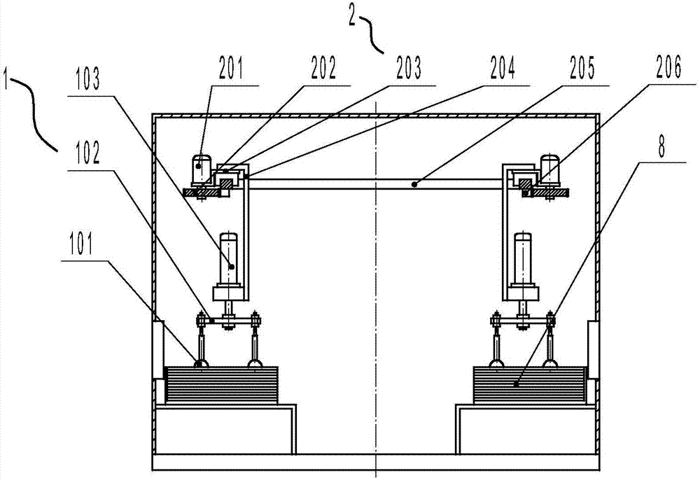
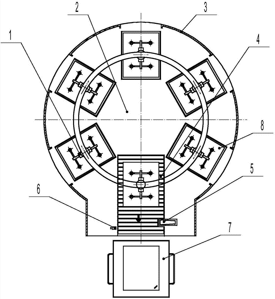
[0040] figure 1 , figure 2 Disclosed in is an automatic binding machine for test papers, which includes a test paper grabbing mechanism 1, a rotating stacking mechanism 2, a casing 3, a test paper transmission mechanism 4, an automatic test paper binding mechanism 5, a transmission positioning sensor switch 6, a test paper receiving device 7, Six examination paper stations 8, control mechanism, examination paper 9 is placed in five examination paper stations in order, and the sixth examination paper station is located on the examination paper conveying mechanism 4, which is used to place stacked examination papers; examination paper grabbing mechanism 1 , the rotary stacking mechanism 2, the test paper transmission mechanism 4, and the test paper automatic binding mechanism 5 are respectively connected with the output ends of the control mechanism. in:
[0041] The examination paper grasping mechanism 1 is located above each examination paper station, and its main function ...
Embodiment 2
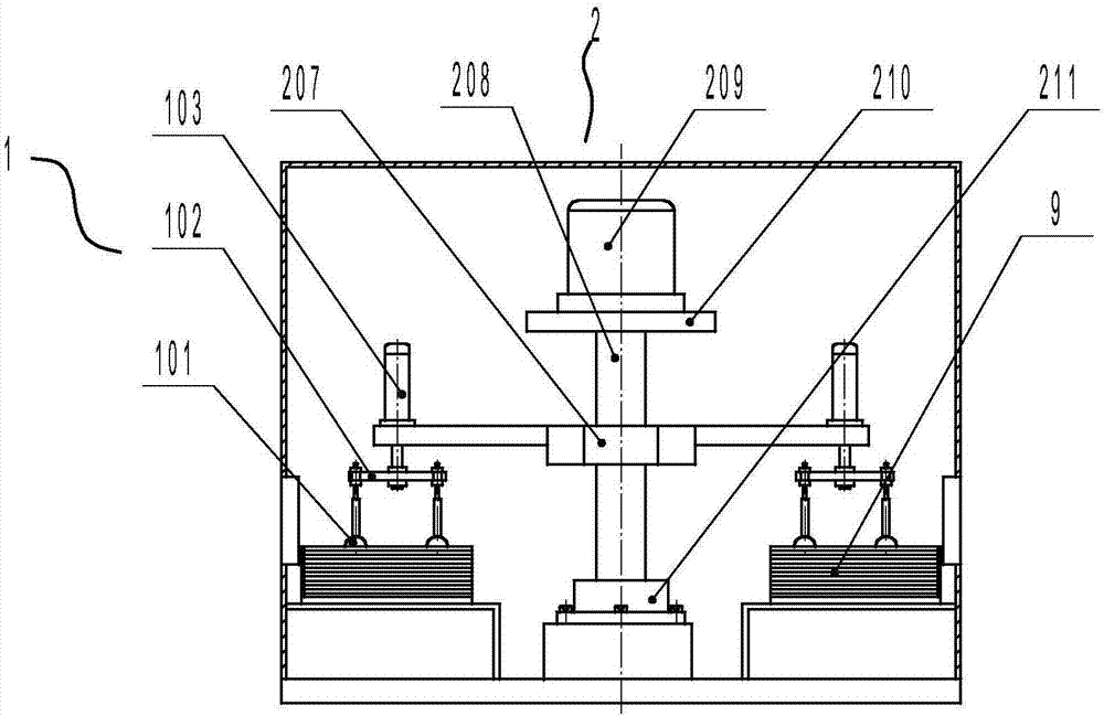
[0049] image 3 , Figure 4 Disclosed in is another automatic binding machine for test papers. The basic structure of the automatic binding machine for test papers is the same as that of Embodiment 1, including a test paper grabbing mechanism 1, a rotating stacking mechanism 2, a casing 3, a test paper transmission mechanism 4, and an automatic test paper binding mechanism. The binding mechanism 5, the transmission positioning sensor switch 6, the test paper receiving device 7, the six test paper stations 8, and the control mechanism, the difference is that the rotating stacking mechanism 2 includes a multi-station support plate 207 and a rotating shaft 208 , rotating motor B209, motor mounting plate 210, rotating bearing seat 211; described multi-station support plate 207 is installed on the rotating shaft 208, and the periphery of this multi-station support plate 207 is connected with each lift cylinder 103 respectively; Described The rotary motor B209 is installed on the m...
PUM
 Abstract
Description
Claims
Application Information
 - R&D
- Intellectual Property
- Life Sciences
- Materials
- Tech Scout
- Unparalleled Data Quality
- Higher Quality Content
- 60% Fewer Hallucinations
Browse by: Latest US Patents, China's latest patents, Technical Efficacy Thesaurus, Application Domain, Technology Topic, Popular Technical Reports.
© 2025 PatSnap. All rights reserved.Legal|Privacy policy|Modern Slavery Act Transparency Statement|Sitemap|About US| Contact US: help@patsnap.com


