Anti-adhesion double-cavity spinning assembly

A double-cavity spinning assembly and anti-adhesion technology, which is applied in the direction of spinneret assemblies, textiles and papermaking, and can solve problems such as contact, unfavorable production, and adhesion

Inactive Publication Date: 2018-01-05
陈慧忠
View PDF0 Cites 0 Cited by
  • Summary
  • Abstract
  • Description
  • Claims
  • Application Information

AI Technical Summary

Problems solved by technology

Because the molten high-temperature polymer melt needs to be transferred and flowed in the spinning assembly, therefore, there will inevitably be contact between the high-temperature melt and the quality inspection of the spinning assembly, and it will inevitably be in the spinning assembly. There is adhesion on the inner wall. Although the inner wall of the spinning assembly can be processed to be smooth enough at present, the polymer adhesion caused by the inner wall surface has been greatly reduced. However, due to the processing accuracy and Due to the limitations of processing technology, it is difficult to make the inner wall completely smooth, which will still cause polymer adhesion; in the prior art, there is also a solution to add a lubricant between the polymer and the inner wall of the spinning component during spinning , which will have a certain anti-adhesion effect, but these added lubricants will inevitably enter the polymer, and then the properties of the polymer and the properties of subsequent spinning will have unpredictable effects, and it is not advisable
Due to the adhesion of the polymer during the spinning process, it is necessary to thoroughly clean the spinning group after the production plan of a batch is not completed. The cleaning of the spinning group will lead to a great consumption of time and cost, and There will still be some dead corners that are difficult to clean, which will adversely affect subsequent production

Method used


Image

  • Anti-adhesion double-cavity spinning assembly

Examples


Embodiment Construction

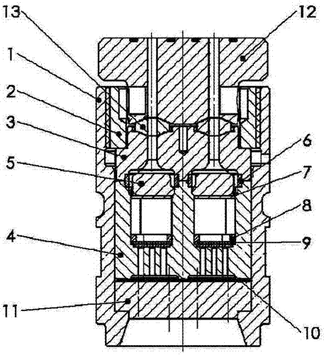
[0031] The present invention will be described in detail below in conjunction with specific embodiments and drawings.

[0032] An anti-adhesion dual-cavity spinning component, which is composed of the following components: component housing 1, locking ring 2, upper cover 3, double-cavity sand cup 4, waist-shaped distribution plate 5, waist-shaped sealing ring 6, pressure sand Plate 7, aluminum sealing ring 8, multi-layer filter screen 9, integral sealing gasket 10, spinneret 11, component connecting block 12, gasket 13; component housing 1 surrounds the entire component and passes through the locking ring 2 The internal components of the module are locked with the module housing 1; the double-cavity sand cup 4 and the upper cover 3 are arranged from bottom to top as follows: multilayer filter screen 9, aluminum sealing ring 8, sand pressing plate 7 and waist The distribution plate 5 is connected by a waist-shaped sealing ring 6. An integral sealing gasket 10 is arranged between t...


PUM

PropertyMeasurementUnit
surface areaaaaaaaaaaa

Abstract

An anti-adhesion double-cavity spinning assembly of the present invention is composed of the following components: assembly housing, locking ring, upper cover, double-cavity sand cup, waist-shaped distribution plate, waist-shaped sealing ring, sand-pressing plate, aluminum Sealing ring, multi-layer filter screen, integral sealing gasket, spinneret, component connecting block, sealing gasket. Concave-convex anti-adhesion structures are provided on the inner wall of the part of the spinning assembly that is in contact with the molten polymer, which can realize the anti-adhesion effect of the polymer melt in the spinning assembly; the mechanism of the concave-convex anti-adhesion mechanism It is: the concave-convex anti-adhesion structure includes concave parts and convex parts, and the convex parts are set higher than the surface of the inner wall of the part, and the direct contact between the high-viscosity polymer melt and the inner wall of the part is reduced by using the supporting effect between points , and under the action of high-temperature and high-pressure melt, a gas suspension is formed to play a self-separating anti-adhesion.

Description

Technical field [0001] The invention relates to the technical field of textiles, in particular to an anti-adhesion dual-cavity spinning assembly. Background technique [0002] The earliest record of the melt spinning process comes from a British patent in 1845. In 1939, melt spinning was used industrially as a production process for manufacturing nylon 66 fibers. The basic process of melt spinning includes material melting, extrusion from the micro holes of the spinneret, and cooling and solidification of the melt stream. The finished filament can be wound into a bobbin or subjected to other processing. In the process of melt spinning, the polymer is fed into the extruder, conveyed by the screw, plasticized, and melted, and then forwarded to the metering pump: the metering polymer is accurately metered to ensure that the polymer melt can flow stably and evenly. The key component of the spinning assembly is that the melt in the spinning assembly is filtered by the filter medium...

Claims


Application Information

Patent Timeline
Patent Type & Authority Applications(China)
IPC IPC(8): D01D4/00D01D4/06
Inventor 陈慧忠
Owner 陈慧忠
Why Eureka
Try Eureka