Fusion dynamic mixer

A technology for dynamic mixers and molten polymers, applied in the direction of mixers, mixers with rotating stirring devices, chemical instruments and methods, etc., can solve problems such as impact, unfavorable production, time and cost consumption

Inactive Publication Date: 2018-03-23
NINGBO FENGHUA FEITIANREN PRECISION MOLD DESIGN CO LTD
View PDF0 Cites 0 Cited by
  • Summary
  • Abstract
  • Description
  • Claims
  • Application Information

AI Technical Summary

Problems solved by technology

[0007] Since the molten high-temperature polymer melt needs to transfer and flow in the spinning component, it is inevitable that the high-temperature melt will be in contact with the spinning component quality inspection, and it will inevitably be on the inner wall of the spinning component. There is adhesion. Although the inner wall of the spinning component can be processed smooth enough at present, the polymer adhesion caused by the inner wall surface problem has been greatly reduced. However, due to the processing accuracy and processing technology However, it is difficult to make the inner wall completely smooth, which will still cause polymer adhesion; in the prior art, there is also a solution to add a lubricant between the polymer and the inner wall of the spinning component during spinning, so that It will have a certain anti-adhesion effect, but these added lubricants will inevitably enter the polymer, and then the properties of the polymer and the properties of subsequent spinning will have unpredictable effects, and it is not advisable
Due to the adhesion of the polymer during the spinning process, it is necessary to thoroughly clean the spinning group after the production plan of a batch is not completed. The cleaning of the spinning group will lead to a great consumption of time and cost, and There will still be some dead corners that are difficult to clean, which will adversely affect subsequent production

Method used


Image

  • Fusion dynamic mixer

Examples


Embodiment 1

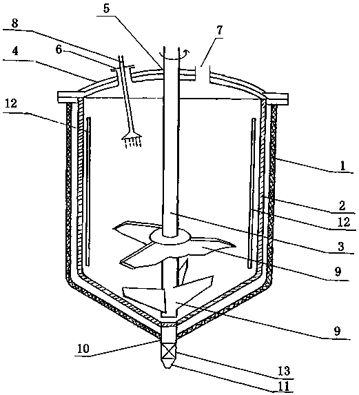
[0035] A melting dynamic mixer, comprising a shell 1, a filter layer 2, and a stirring shaft 3; a cover 4 is arranged on the upper part of the shell 1, and a stirring shaft hole 5, a monomer suction hole 6 and a feeding material are arranged on the cover 4 Hole 7, the stirring shaft 3 extends into the inside of the housing 1 through the stirring shaft hole 5, the monomer suction hole 6 is provided with a monomer suction device 8, and the feed hole 7 is connected with the external molten polymer supply device; the filter layer 2 It is set close to the inner wall of the shell 1, and there is a gap between it and the inner wall of the shell 1; several stirring blades 9 are set on the stirring shaft 3, and the stirring shaft 3 is connected with an external drive device; the bottom of the shell 1 is provided with a molten polymer discharge Port 10, the molten polymer discharge port 10 is connected to the discharge pipe 11; the surface of the stirring shaft 3, the stirring blade 9, t...


PUM

PropertyMeasurementUnit
surface areaaaaaaaaaaa

Abstract

The invention discloses a fusion dynamic mixer which comprises a shell body, a filtering layer and a stirring shaft, wherein a cover body is arranged at the upper part of the shell. Concave-convex anti-adhesion structures are arranged on the surfaces of components which are arranged in the mixer and can contact molten polymer, so that an anti-adhesion effect of polymer melt in a spinning assemblyis achieved; an action mechanism of the concave-convex anti-adhesion mechanisms is that each concave-convex anti-adhesion mechanism comprises a concave part and a convex part, the convex part is higher than the surfaces of the components, direct contact between the polymer melt and the surfaces of the components is reduced by supporting effects among points, and furthermore, a gas suspension effect can be formed under the action of high-temperature and high-pressure melt to achieve self-separation anti-adhesion.

Description

technical field [0001] The invention relates to the technical field of textiles, in particular to a melting dynamic mixer. Background technique [0002] The earliest record of the melt spinning process comes from a British patent in 1845. In 1939, melt spinning was industrialized as a production process for the manufacture of nylon 66 fibers. The basic process of melt spinning includes material melting, extrusion from the micropores of the spinneret, and cooling and solidification of the melt stream. The finished filament can be wound into a bobbin or otherwise processed. In the process of melt spinning, the polymer is fed into the extruder, conveyed by the screw, plasticized, melted and then forwarded to the metering accumulator: the metering polymer ensures that the melt of the polymer can flow stably and evenly into the In the spinning assembly of the key component, the melt in the spinning assembly is filtered by the filter medium to remove impurities and air bubbles,...

Claims


Application Information

Patent Timeline
Patent Type & Authority Applications(China)
IPC IPC(8): B01F7/18B01F15/00B01F15/02B01D29/03
CPCB01D29/03B01F27/90B01F35/45B01F35/187B01F35/718B01F35/71805
Inventor 华巧波
Owner NINGBO FENGHUA FEITIANREN PRECISION MOLD DESIGN CO LTD
Why Eureka
Try Eureka