Pressure slide sleeve control type gas well continuous drainage gas production plunger piston

A water drainage and gas recovery, control technology, applied in the direction of production fluid, earthwork drilling, wellbore/well components, etc., can solve the problems of increased workover and fishing operations, discontinuous production, complex process flow, etc.

Active Publication Date: 2018-01-05
XI'AN PETROLEUM UNIVERSITY
View PDF10 Cites 15 Cited by
  • Summary
  • Abstract
  • Description
  • Claims
  • Application Information

AI Technical Summary

Problems solved by technology

However, there are still some problems, such as complex technological process, discontinuous production, long shut-in time, etc.
[0004] At present, the commonly used drainage and gas production plungers include solid rod plungers, liner plungers, bypass plungers and split plungers. The common disadvantage of them is that they cannot control the lifting fluid volume of the plunger in a single working cycle. , and it is impossible to make targeted adjustments for different well conditions
When there is too much fluid at the bottom of the well, the upward resistance of the plunger is relatively large, and the plunger may fail to reach the wellhead, which will increase redundant workover and fishing operations; when the fluid at the bottom of the well is less, the recovery of formation pressure is low. The liquid leakage is serious during the upward movement of the plunger, and the liquid lifting efficiency is low

Method used


Image

  • Pressure slide sleeve control type gas well continuous drainage gas production plunger piston
  • Pressure slide sleeve control type gas well continuous drainage gas production plunger piston
  • Pressure slide sleeve control type gas well continuous drainage gas production plunger piston

Examples


Embodiment Construction

[0017] The present invention is described in detail below in conjunction with accompanying drawing.

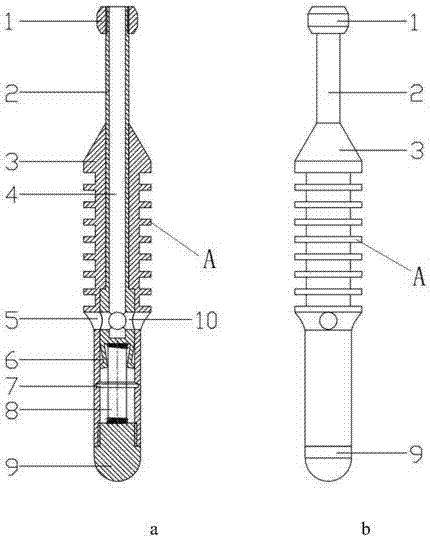
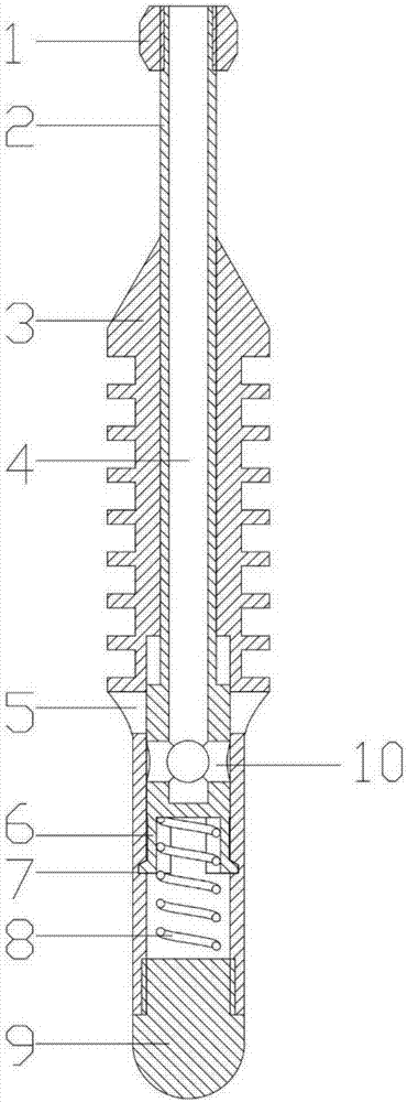
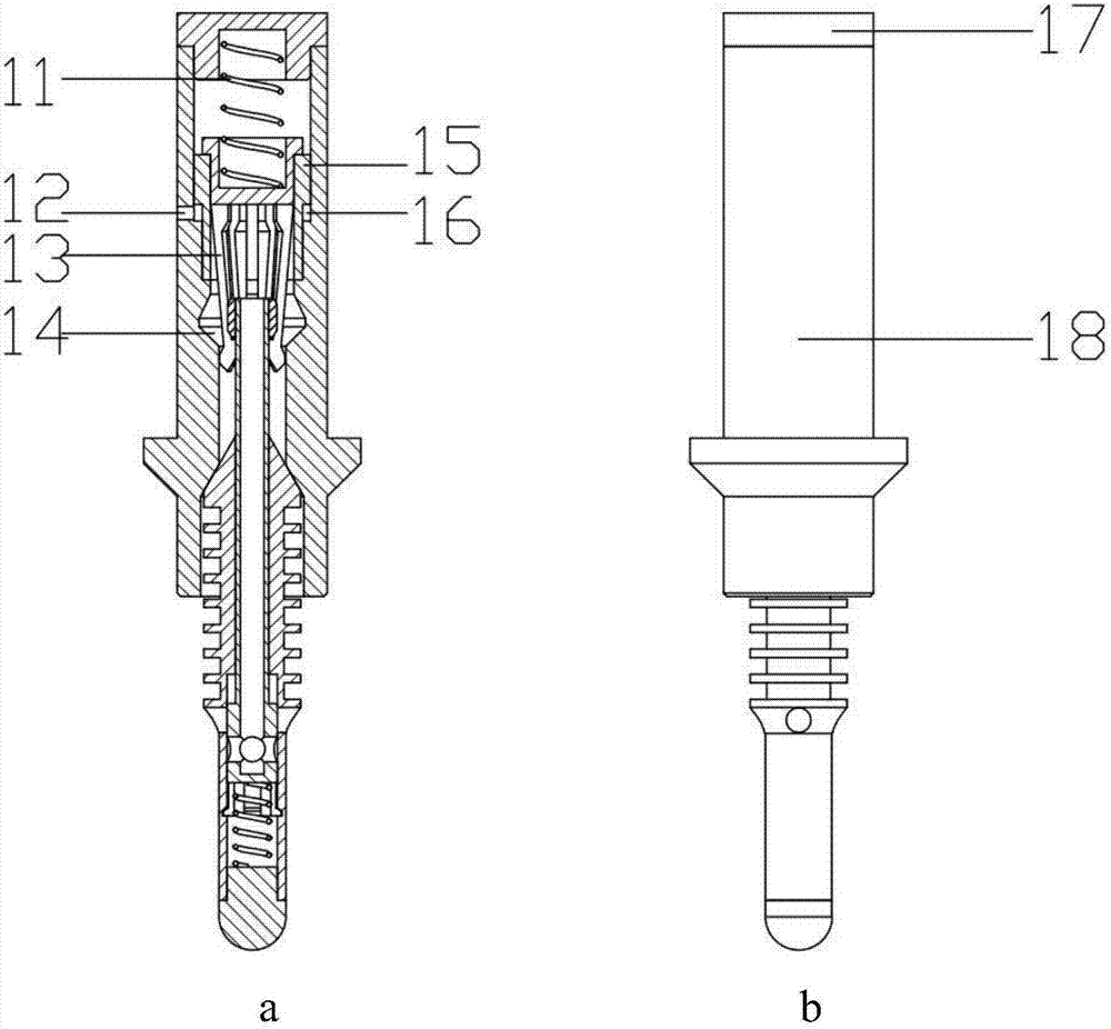
[0018] refer to figure 1 , a pressure sliding sleeve control type gas well continuous drainage and gas production plunger, comprising a plunger body 3 of hollow structure, the outer wall of the plunger body 3 is provided with uniformly distributed grooves A, and the outer wall of the plunger body 3 is also provided with circumferentially evenly distributed four A plunger body through hole 5, the inner wall of the plunger body 3 is provided with a groove 7; the plunger body 3 hollow inner cavity is successively set with a sliding sleeve 2 and a spring 8, and the spring 8 is connected with a threaded spring seat 9; the sliding sleeve 2. The upper part is a hollow structure with four radial through holes 10 evenly distributed in the circumferential direction. The bottom of the sliding sleeve 2 is provided with elastic claws 6. The upper end of the sliding sleeve is connected to t...


PUM


Abstract

The invention relates to a pressure slide sleeve control type gas well continuous drainage gas production plunger piston. Grooves are uniformly distributed in the outer wall of a plunger piston body of a hollow structure; the outer wall of the plunger piston body is also provided with four plunger piston body in uniform distribution in the circumferential direction; the inner wall of the plunger piston body is provided with a groove; a slide sleeve and a spring are sequentially arranged in a hollow inner cavity of the plunger piston body in a sleeved way; the upper part of the slide sleeve isof a hollow structure and is provided with four slide sleeve radial through holes in the uniform distribution in the circumferential direction; the bottom of the slide sleeve is provided with an elastic jack catch; the upper end of the slide sleeve is connected with a fishing head through screw threads; the upper part of the fishing head is connected with the inside of a catcher body; one end of the spring is abutted against the lower end of the slide sleeve; and the other end of the spring is abutted against the upper end of a spring seat and is compressed in the inner cavity of the plunger piston body. The fast descending of the plunger piston in accumulated liquid can be realized through the opening of a passage in the plunger piston; the continuous production without well shut-in of the plunger piston drainage gas production is realized; different springs in the plunger piston can be replaced by aiming at the well status conditions of different wells; the liquid lifting quantity ofeach single work period with different caliber is controlled; the customization aiming at the plunger piston with different well status conditions is realized; and the optimum value of the work efficiency is reached.

Description

technical field [0001] The invention relates to a downhole drainage and gas recovery tool in the field of petroleum and natural gas exploitation. It particularly relates to a pressure sliding sleeve control type gas well continuous drainage gas production plunger. technical background [0002] Gas wells will more or less produce some liquid during production. When the flow rate of gas in the wellbore is greater than the critical flow rate of liquid carrying, the liquid is carried to the ground by the gas in the form of droplets, and the gas is in a continuous phase while the liquid is in a discontinuous phase; When the gas flow rate is low and cannot provide enough energy to make the liquid in the wellbore flow out of the wellhead, the liquid will flow in the opposite direction to the gas and accumulate at the bottom of the well, eventually resulting in bottom-hole fluid accumulation. At present, the proportion of water-producing gas reservoirs in China is relatively large,...

Claims


Application Information

Patent Timeline
Patent Type & Authority Applications(China)
IPC IPC(8): E21B43/12E21B34/08E21B31/18F04B47/00F04B53/12F04B53/14
Inventor 徐建宁李庭玉高素娟朱端银
Owner XI'AN PETROLEUM UNIVERSITY
Why Eureka
Try Eureka