Scrap steel shear fast hydraulic system

A hydraulic system, fast technology, applied in the direction of fluid pressure actuating device, servo motor, servo meter circuit, etc., can solve the problems of increasing fault occurrence, difficult dynamic compensation, large impact of hydraulic and mechanical devices, etc. , the effect of faster response, simple structure

Active Publication Date: 2017-12-05
HUBEI LIDI MACHINE TOOL
View PDF9 Cites 0 Cited by
  • Summary
  • Abstract
  • Description
  • Claims
  • Application Information

AI Technical Summary

Problems solved by technology

However, in this hydraulic control structure, there is a problem of large hydraulic shock, and an additional set of two-way cartridge directional valves for realizing differential rapid descent, such as the two-way cartridge directional valve 17 in the figure, is additionally provided. Increased cost and increased chances of failure during work trips
Moreover, it is also difficult to realize the rapid downlink of confluence and differential, and the work efficiency is low.
[0004] Chinese patent document CN205013408U describes a fully differential hydraulic control device for scrap steel shears, which solves the problems of complex structure, high failure rate, serious leakage, low efficiency and unreliable action in the existing slide valve hydraulic control system
The existing problem is: the differential mode of the pressing cylinder and the shearing cylinder is performed by two differential valves 14 and 22, which cannot realize dynamic flow distribution, that is, when the oil cylinder goes down too fast, the structure is difficult to carry out dynamic compensation
The return stroke is realized by filling the oil in the plug chamber of the pressing cylinder to the rod chamber of the shearing cylinder through the plug-in directional valve 23. The structure is relatively complicated. When the dynamic balance between chamber A and chamber B of the cartridge directional valve 23 is not established, the pressing head and shearing head will slide down quickly without support
During the return journey, there is a lack of buffer measures, which will have a greater impact on the hydraulic and mechanical devices

Method used


Image

  • Scrap steel shear fast hydraulic system
  • Scrap steel shear fast hydraulic system
  • Scrap steel shear fast hydraulic system

Examples


Embodiment Construction

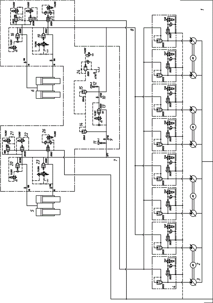
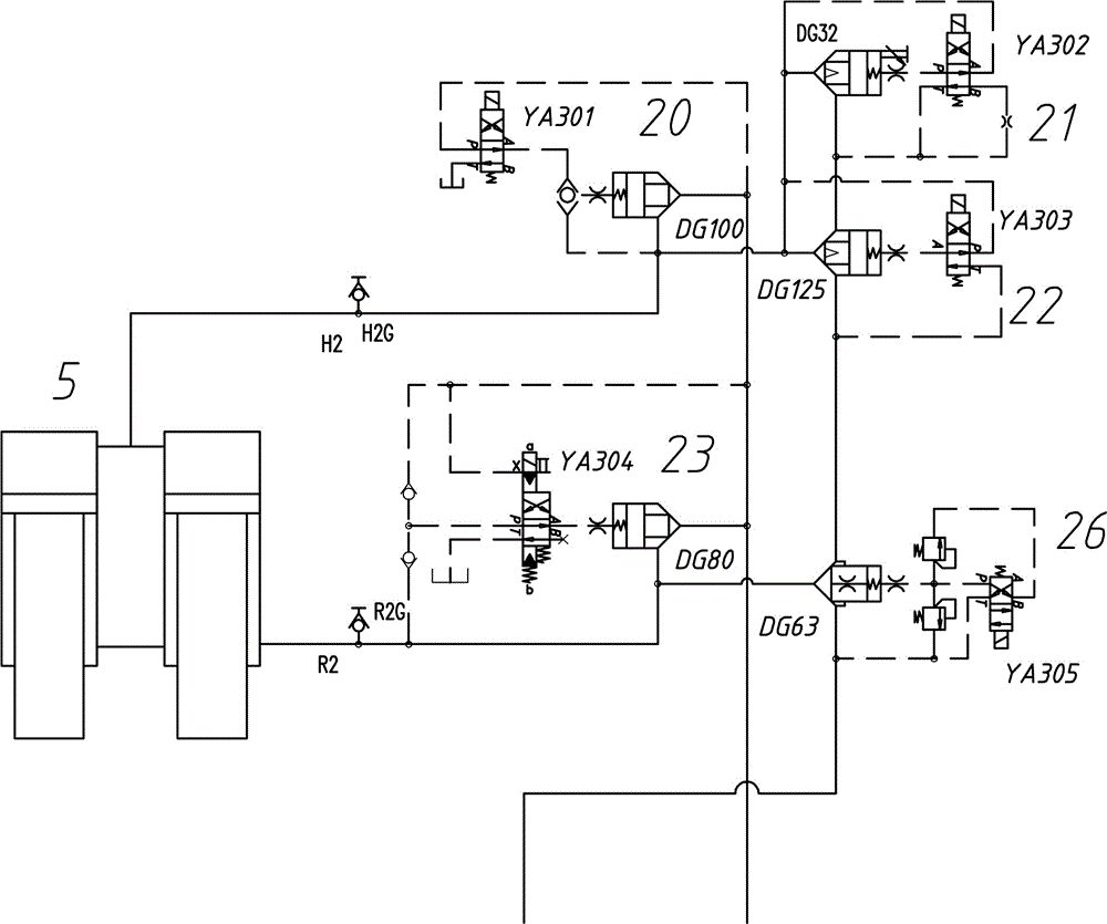
[0037] Such as Figure 1~5 Among them, a rapid hydraulic system for scrap steel shearing, a plurality of oil pumps 3 are respectively connected to the first oil inlet 7 and the second oil inlet 8; this structure facilitates the control of hydraulic oil flow according to working conditions.

[0038]In a preferred solution, the plurality of oil pumps 3 are respectively connected to the motor 2, the motor 2 adopts a frequency conversion double extension shaft motor, and each double extension shaft motor is connected to two oil pumps. Based on this structure and dynamic configuration according to working conditions, energy consumption can be further saved.

[0039] The system of the present invention is conventionally used in the rapid hydraulic system of 800-ton scrap steel shears. When it is used in 1250-ton scrap steel shears, the size of the plug-in directional valve does not need to be changed, only two sets of oil pumps and motor units need to be added to meet the requiremen...


PUM


Abstract

The invention provides a rapid hydraulic system of a scrap steel shear. Multiple oil pumps are connected with a first oil inlet and a second oil inlet respectively. The first oil inlet is connected with a plug cavity of a shear cylinder through an eighth plug-in mounting directional valve bank. The plug cavity of the shear cylinder is further connected with an oil tank through a ninth plug-in mounting directional valve bank and a tenth plug-in mounting directional valve bank. The first oil inlet is connected with a rod cavity of the shear cylinder through an eleventh plug-in mounting directional valve bank. The rod cavity of the shear cylinder is connected with the oil tank through a third plug-in mounting overflow valve bank. The second oil inlet is connected with the plug cavity of the shear cylinder through a fourth plug-in mounting directional valve bank. A plug cavity of a pressing cylinder is connected with the oil tank through a fifth plug-in mounting directional valve bank and the sixth plug-in mounting directional valve bank. The second oil inlet is connected with a rod cavity of the pressing cylinder through a seventh plug-in mounting directional valve bank. The rod cavity of the pressing cylinder is further connected with the oil tank through a second plug-in mounting overflow valve bank. By the adoption of the multiple oil pumps for supplying oil at the same time, input hydraulic oil mass and power can be manually adjusted according to working conditions, configuration is flexible, and energy consumption is low.

Description

technical field [0001] The invention relates to the field of hydraulic control systems, in particular to a fast hydraulic system for steel scrap shears. Background technique [0002] The existing scrap steel shearing hydraulic system uses high and low pressure pump heads to switch the pressure, which has high energy consumption, slow operation speed of the scrap steel shearing oil cylinder, low shearing efficiency of scrap steel shearing, and high manufacturing and operating costs of the equipment. [0003] Chinese patent document CN201137603Y discloses a large-scale shearing machine hydraulic control valve group, which uses a two-way plug-in directional valve to control the hydraulic oil, and has the functions of oil cylinder support and overload protection. The hydraulic oil flux is large, the volume is small, and the energy saving energy consumption. However, in this hydraulic control structure, there is a problem of large hydraulic shock, and an additional set of two-wa...

Claims


Application Information

Patent Timeline
Patent Type & Authority Patents(China)
IPC IPC(8): F15B11/17F15B11/20
CPCF15B11/17F15B11/20F15B2211/40523F15B2211/4053F15B2211/8606
Inventor 李明波林高刘东旭覃棚
Owner HUBEI LIDI MACHINE TOOL
Why Eureka
Try Eureka