Plunger piston and oil and gas well structure

A plunger and structure technology, applied in the field of natural gas and oil exploitation, can solve the problems of plunger resistance and the inability of the plunger to descend, and achieve the effect of reducing descending resistance and improving production time

Pending Publication Date: 2019-04-19
成都百胜野牛科技有限公司
View PDF0 Cites 0 Cited by
  • Summary
  • Abstract
  • Description
  • Claims
  • Application Information

AI Technical Summary

Problems solved by technology

[0005] Because the packing sheet is always in contact with the inner wall of the well to form a seal under the action of the elastic member, the plunger is subjected to great resistance when it goes down
This makes the plunger need to go down for a long time to reach the bottom of the well, and may even prevent the plunger from going down to the bottom of the well

Method used


Image

  • Plunger piston and oil and gas well structure
  • Plunger piston and oil and gas well structure
  • Plunger piston and oil and gas well structure

Examples


Embodiment 1

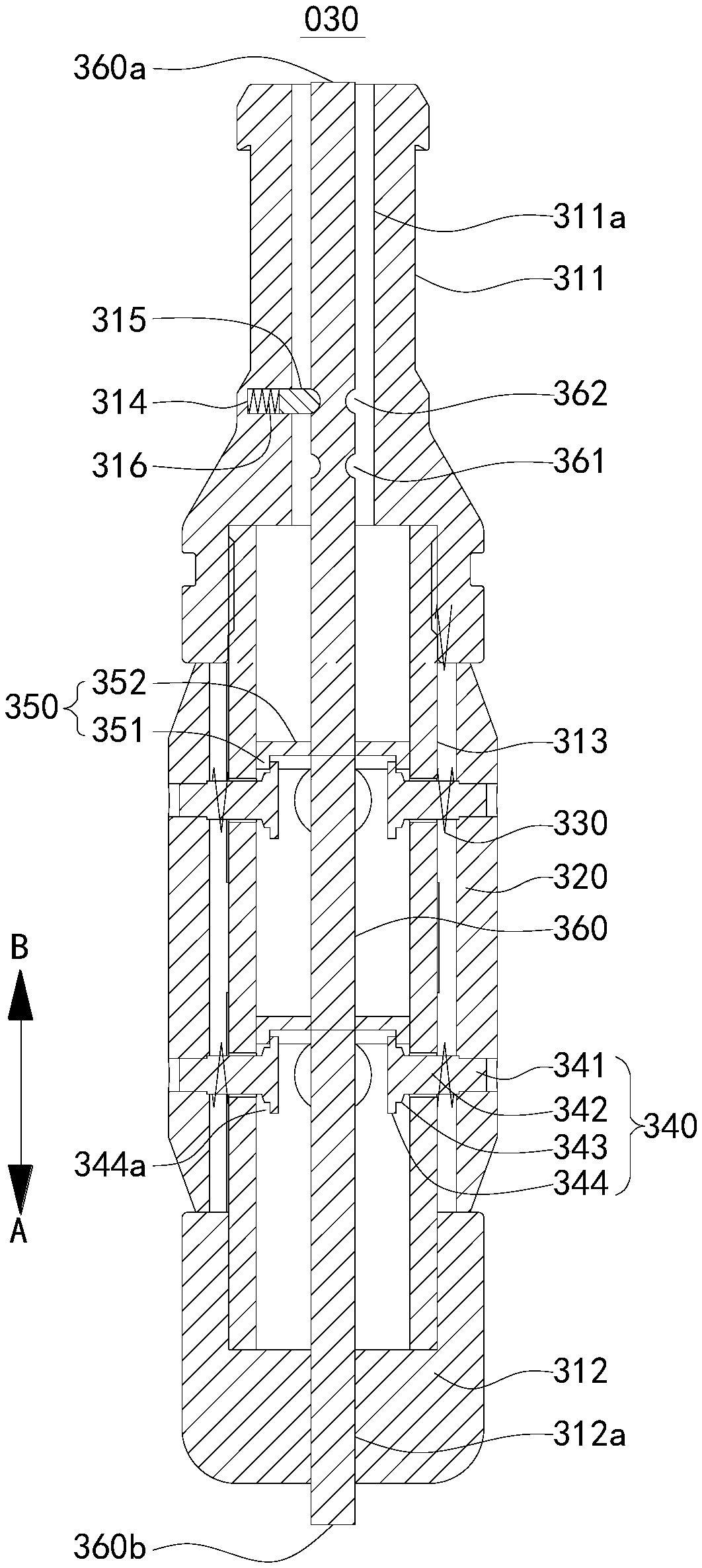
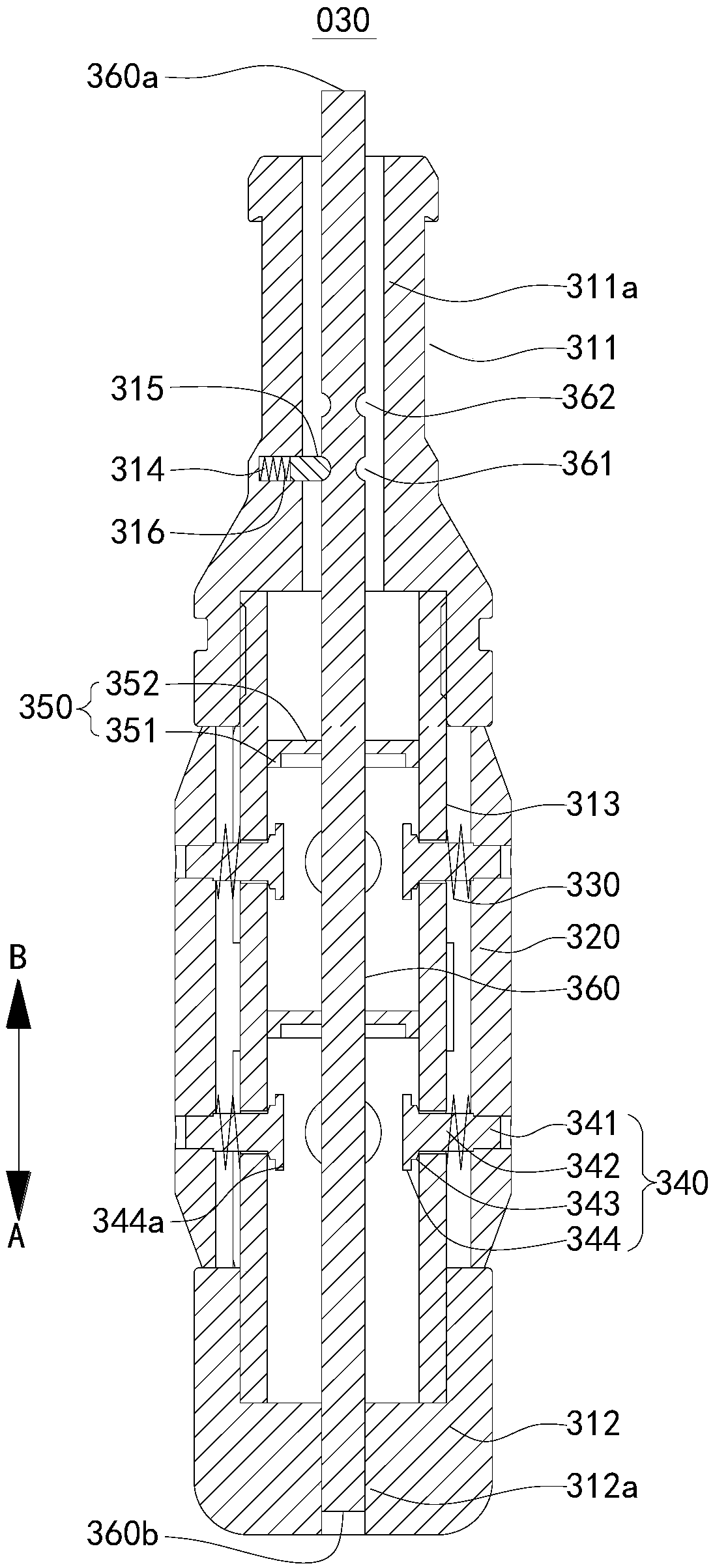
[0039] figure 1 A schematic diagram of the structure of the locking member 350 in the plunger 030 provided in this embodiment when it is in the unlocked position; figure 2 This embodiment provides a schematic diagram of the structure of the locking member 350 in the plunger 030 when it is in the locked position. The plunger 030 includes a core tube 310 , a plurality of sealing pieces 320 , an elastic member 330 , a guide post 340 , a locking member 350 and an actuating part 360 .

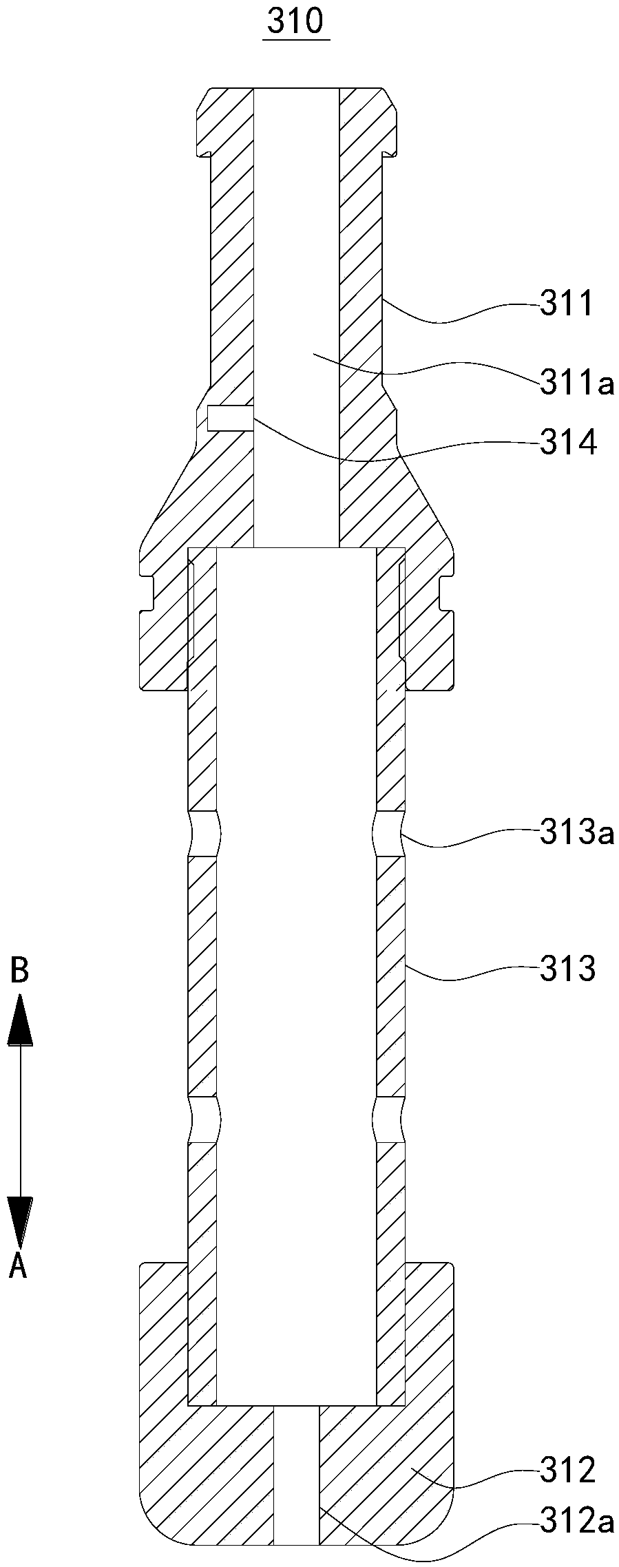
[0040] image 3 A schematic structural view of the core tube 310 of the plunger 030 provided in this embodiment. In this embodiment, the core tube 310 is a tubular member extending along the AB direction. The core tube 310 includes a first end 311 , a second end 312 and a tube body 313 . Two ends of the core tube 310 are respectively inserted into the first end 311 and the second end 312 , and screwed to the first end 311 and the second end 312 . A first through hole 311 a extending along the ...

Embodiment 2

[0051] Figure 4 In the plunger 030 provided for this embodiment, the state diagram when the locking member 350 is in the locking position; Figure 5 In the plunger 030 provided for this embodiment, a state diagram of the lock member 350 at the unlocked position. Please refer to Figure 4 and Figure 5 , the plunger 030 provided in this embodiment is basically the same as that in Embodiment 1, the main difference is that the first joint part 361, the second joint part and the third joint part 362 in this embodiment 1 are triggered by the holding mechanism 010 replace.

[0052] In this embodiment, the actuating part 360 includes a first part 363 and a second part 364 which are independent from each other. The first portion 363 and the second portion 364 are arranged at intervals along the AB direction. The end of the first part 363 away from the second part 364 is the first end 360a; the end of the second part 364 away from the first part 363 is the second end 360b. The fir...

Embodiment 3

[0060] Figure 9 A schematic structural diagram of the oil and gas well structure 01 provided in this embodiment. Please refer to Figure 9 , the oil and gas well structure 01 provided in this embodiment includes the plunger 030 described in Embodiment 1 or Embodiment 2. The oil and gas well structure 01 also includes a wellhead pipeline 11 located on the ground, and a wellway 12 arranged below the ground and communicating with the wellhead pipeline 11 . An upper impact part 13 is arranged on the top of the wellhead pipeline 11 , and a lower impact part 14 is arranged on the bottom of the hoistway 12 . The inner diameter of the wellhead pipeline 11 is smaller than the inner diameter of the shaft 12 . The plunger 030 can go down from the top of the wellhead pipeline 11 to the bottom of the wellhead pipeline 12 , and the plunger 030 can also go up from the bottom of the wellhead pipeline 12 to the top of the wellhead pipeline 11 .

[0061] After the plunger 030 goes up into ...


PUM


Abstract

The invention relates to the technical field of natural gas and oil exploitation, and discloses a plunger piston and an oil and gas well structure. The plunger piston runs in an oil and gas well. Theinner diameter of a well mouth pipeline of the oil and gas well is smaller than that of a well shaft. After the plunger piston moves upwards to enter the well mouth pipeline, sealing spacers radiallymove inwards under extrusion of the inner wall of the well mouth pipeline, and then a limiting gap is formed between a limiting portion and the inner circumferential face of a core pipe. At the moment, a locking part moves from the unlocking position to the locking position under driving of an actuating part, the locking part is embedded into the limiting gap to prevent the sealing spacers from radially and outwards moving, and then the diameter of the plunger piston is smaller than the inner diameter of the well shaft. Therefore, the downward moving resistance of the plunger piston is significantly decreased, the plunger piston can quickly move downwards to the well bottom and even can move downwards to the well bottom in a well opening state; and when the plunger piston moves downwards to the well bottom, the locking part moves from the locking position to the unlocking position under driving of the actuating part, and then the plunger piston can move upwards.

Description

technical field [0001] The invention relates to the technical field of natural gas and oil exploitation, in particular to a plunger and an oil and gas well structure. Background technique [0002] During the development of natural gas or oil wells, in order to increase the production of natural gas or oil, it is necessary to lift the liquid at the bottom of the well to the surface. [0003] Plunger lift technology has been widely used in the development of natural gas or oil wells. The existing plunger includes a plurality of spacers, and these spacers are always in contact with the inner wall of the hoistway for friction under the action of the elastic member to form a seal. In the shut-in state, the plunger goes down to the bottom of the well. When the well is opened, the pressure generated by the fluid below the plunger drives the plunger upward, the liquid above the plunger is lifted by the plunger, and the fluid above the plunger is discharged when the plunger ascends...

Claims


Application Information

Patent Timeline
Patent Type & Authority Applications(China)
IPC IPC(8): F04B47/12F04B53/02F04B53/14E21B43/00
CPCF04B47/12E21B43/00F04B53/02F04B53/14F04B53/143
Inventor 刘书豪唐勇陈俊宏苏诗策刘树飞
Owner 成都百胜野牛科技有限公司
Why Eureka
Try Eureka