Project counterweight device
A counterweight device and project technology, applied in the direction of measuring devices, instruments, measuring instrument components, etc., can solve the problems of high production cost and difficult processing, and achieve high versatility, good rigidity, easy mutual combination and modularization. Effect
- Summary
- Abstract
- Description
- Claims
- Application Information
AI Technical Summary
Problems solved by technology
Method used
Image
Examples
Embodiment 1
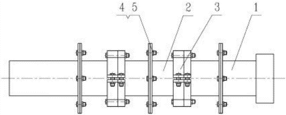
[0028] Such as figure 1 As shown, the structure of this embodiment includes a counterweight main beam and a counterweight 3 arranged on the counterweight main beam. The counterweight 3 has multiple pieces, which are ring-shaped structures sleeved on the counterweight main beam. , or stacked on the counterweight main beam as a square block structure.
[0029] In this embodiment, the cross-section of the counterweight main beam is circular, including a connecting main beam 1 and a plurality of butt joint main beams 2 sequentially connected, and the butt joint main beam 2 at the end is connected to the connecting main beam 1, The counterweight 3 is a semicircular clamp structure, which is sheathed on the butt main girder 2 .
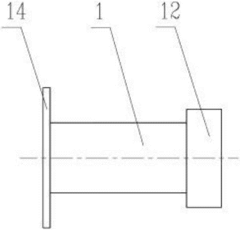
[0030] In this embodiment, one end of the connecting main beam 1 is provided with a base 12 connected to the main structure to be counterweighted, and the other end is provided with a connecting flange 14, such as figure 2 As shown, one end of the docked...
Embodiment 2
[0035] On the basis of Embodiment 1, another way can be adopted for the positioning of the connecting flange and the butt flange: that is, the end face of the connecting flange is provided with a positioning boss, and the end face of the butt flange is provided with a positioning boss Compatible locating slots, such as Figure 6 shown.
[0036] The above-mentioned first and second embodiments are mainly aimed at the situation that the counterweight main beam of cylindrical structure is required, and the counterweight main beam adopts a combined structure, which can be used for counterweighting at will and can be recycled. According to the overall structural length requirements, the counterweight girder is decomposed into connecting girder 1 and several docking girders 2, and the diameter of butt girder 2 can be selected according to the actual situation. Generally, the small diameter butt girder 2 is used for matching Reconnect the top of the unit. One end of connecting main...
Embodiment 3
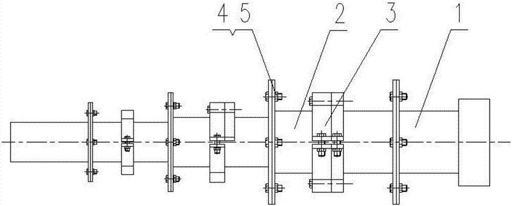
[0039] On the basis of the first embodiment above, the butt main girder can also be of different diameters, such as figure 2 shown.
[0040] For the case of using different diameters, the diameter of the butt main beam connected to the connecting main beam 1 is the largest, and the more it extends to the other end, the smaller the diameter of the butt main beam is, and the number of counterweights on each butt main beam can be the same , can also be different, the combination of counterweights needs to be carried out according to the actual counterweight requirements, such as figure 2 shown.
PUM
 Abstract
Description
Claims
Application Information
 - R&D
- Intellectual Property
- Life Sciences
- Materials
- Tech Scout
- Unparalleled Data Quality
- Higher Quality Content
- 60% Fewer Hallucinations
Browse by: Latest US Patents, China's latest patents, Technical Efficacy Thesaurus, Application Domain, Technology Topic, Popular Technical Reports.
© 2025 PatSnap. All rights reserved.Legal|Privacy policy|Modern Slavery Act Transparency Statement|Sitemap|About US| Contact US: help@patsnap.com


