
Bearing anti-fouling capability testing device

A capability test and bearing technology, applied in the field of bearing anti-fouling ability test equipment, can solve the problems of long experimental process, high cost, inability to measure and transform bearings, etc., achieve good clamping effect, low overall hardness, and not easy to distribute uniformly dithering effect

Inactive Publication Date: 2018-01-05
JIANGYIN JIB WD PRECISION
View PDF0 Cites 0 Cited by
  • Summary
  • Abstract
  • Description
  • Claims
  • Application Information

AI Technical Summary

Problems solved by technology

[0002] For roller bearings, they are often used in some harsh working conditions. The production debris, sediment, impurities, etc. in the environment often have a certain impact on the rotation of the bearing, and the resistance of the bearing Contamination ability is often used as a performance index of bearings, which is closely related to the structure of bearings and the quality of bearing sealing components. Therefore, it is necessary to carry out pollution tests on bearings when manufacturing and finalizing bearings. This not only tests the anti-contamination performance of bearings, but also provides Provide relevant data for the improvement of bearings; while the traditional bearing anti-fouling ability test is generally installed directly in the actual working condition, disassembled after running for a period of time for detection or directly used until scrapped to measure its rotation life, so that the experimental process Longer and more costly, it is impossible to measure and modify the bearing in real time

Method used


Image

  • Bearing anti-fouling capability testing device
  • Bearing anti-fouling capability testing device

Examples


Embodiment Construction

[0028] The present invention is described in further detail now in conjunction with accompanying drawing. These drawings are all simplified schematic diagrams, which only illustrate the basic structure of the present invention in a schematic manner, so they only show the configurations related to the present invention.

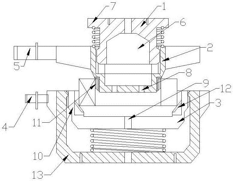
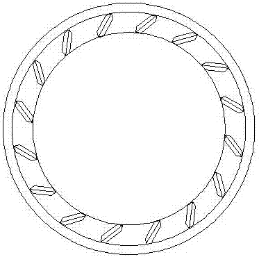
[0029] Such as figure 1 and figure 2 As shown, the present invention is a bearing anti-fouling ability testing equipment, including a base, a bearing inner frame clamp and a bearing outer frame clamp are rotatably connected to the base, and the bearing inner frame clamp The clamp is set on the upper part of the bearing outer frame clamp;

[0030] The bearing inner frame clamp includes an upper rotating base on which a sliding sleeve is sleeved. The sliding sleeve is a cylindrical shell structure with an open top, and the upper rotating base passes through the sliding sleeve. The open end of the sliding sleeve is inserted into the cylindrical housing, and t...


PUM


Abstract

The invention relates to a bearing anti-pollution ability testing device, which comprises a base on which a bearing inner frame clamp and a bearing outer frame clamp are rotatably connected; wherein the bearing inner frame clamp includes an upper rotating base, A sliding sleeve is sleeved on the upper rotating base. The sliding sleeve is a cylindrical shell structure with an open top. The rotating base is inserted into the cylindrical shell through the opening end of the sliding sleeve; the side wall of the sliding sleeve corresponds to the closed end position. A bearing compression ring is provided on the outer wall of the bearing compression ring, and an elastic deformation ring A is provided on the outer wall of the bearing compression ring; a limit ring is also provided on the rotating base, and a push ring is also provided on the outer wall of the opening end of the sliding sleeve. The ring and the push ring are elastically connected by a stretching spring; the bearing outer frame clamp includes a lower rotating base, and the lower rotating base includes a lower rotating sleeve, and a rotating disc is slidably connected to the lower rotating sleeve, and the outer periphery of the rotating disc An annular support ring is provided, and an elastic deformation ring B is provided on the inner wall of the support ring.

Description

technical field [0001] The invention relates to a bearing anti-pollution ability testing equipment, which belongs to the field of bearing testing equipment. Background technique [0002] For roller bearings, they are often used in some harsh working conditions. The production debris, sediment, impurities, etc. in the environment often have a certain impact on the rotation of the bearing, and the resistance of the bearing Contamination ability is often used as a performance index of bearings, which is closely related to the structure of bearings and the quality of bearing sealing components. Therefore, it is necessary to carry out pollution tests on bearings when manufacturing and finalizing bearings. This not only tests the anti-contamination performance of bearings, but also provides Provide relevant data for the improvement of bearings; while the traditional bearing anti-fouling ability test is generally installed directly in the actual working condition, disassembled afte...

Claims


Application Information

Patent Timeline
Patent Type & Authority Applications(China)
IPC IPC(8): G01M13/04
Inventor 程万丁沈强
Owner JIANGYIN JIB WD PRECISION
Learn More