Design method of electromagnetic resonant energy transmission system of forward shunt coil

A technology for system design and energy transmission, applied in current collectors, electric vehicles, electrical components, etc., can solve problems such as energy consumption and system complexity, and achieve the effect of suppressing frequency splitting

Active Publication Date: 2018-01-05
HENAN NORMAL UNIV
View PDF2 Cites 5 Cited by
  • Summary
  • Abstract
  • Description
  • Claims
  • Application Information

AI Technical Summary

Problems solved by technology

However, these additional circuits complicate the system and consume additional power

Method used


Image

  • Design method of electromagnetic resonant energy transmission system of forward shunt coil
  • Design method of electromagnetic resonant energy transmission system of forward shunt coil
  • Design method of electromagnetic resonant energy transmission system of forward shunt coil

Examples


Embodiment Construction

[0046] The design method of the forward parallel coil electromagnetic resonance energy transmission system will be described below with reference to the accompanying drawings.

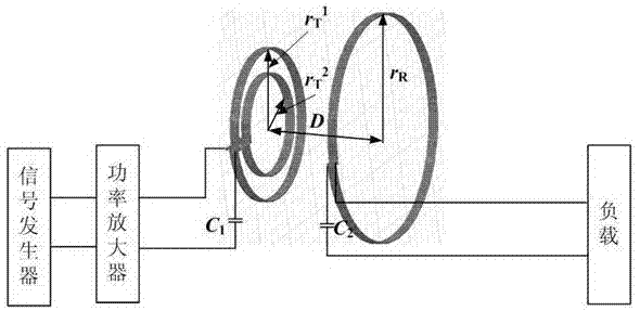
[0047] figure 1 It is a schematic diagram of the WPT / MRC system structure.

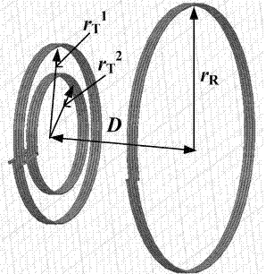
[0048] Such as figure 1 As shown, the WPT / MRC system includes a signal generator, a power amplifier, a ray coil (a double forward parallel coil composed of two forward coils), a receiving coil (unidirectional coil), and an adjustable capacitor C 1 and adjustable capacitor C 2 and load.

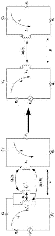
[0049] figure 2 is the equivalent circuit diagram of the WPT / MRC system.

[0050] Such as figure 2 As shown, the inductances of the two forward coils at the transmitting end are L t 1 and L t 2 , the inductance of the unidirectional coil at the receiving end is L r ;The mutual inductance between the two forward coils is M 12 ; The mutual inductance between the two forward coils and the one-way coil at the receiving end is M 1 (D...


PUM


Abstract

The invention discloses a design method of an electromagnetic resonant energy transmission system of a forward shunt coil, relates to a dual-forward shunt resonant coil manufacturing method applied towireless electric energy transmission, and mainly solves the problem of low system transmission efficiency caused by frequency splitting in near distance energy transmission of the wireless electricenergy transmission system. A dual-layer wound transmuting coil is designed; equivalently, internal coils with a certain number of turns are wound in the internal space of the original single-layeredone-way wound transmitting coil, so that external coils and the internal coils can be connected ''in a connection mode of head and head, and end and end'' to form the dual-forward shunt structure; andby virtue of the dual-forward shunt coil structure, sharp change of coupling strength between receiving and transmitting coils can be suppressed, influence generated by frequency splitting in near distance energy transmission to the system transmission efficiency can be lowered, and the transmission efficiency in the position of resonant frequency in near distance energy transmission of wirelesselectric energy transmission can be improved.

Description

technical field [0001] The invention relates to a design method of a forward parallel coil electromagnetic resonance energy transmission system. Background technique [0002] Magnetically coupled resonant wireless power transfer (wireless power transfer via magneticresonant coupling, WPT / MRC) technology has the advantages of medium transmission distance, high transmission efficiency, and the ability to transmit power through non-magnetic barriers, making it expected to replace batteries as the Sensor nodes in the network are powered wirelessly. However, the transmission efficiency of the magnetically coupled resonant wireless power transmission system varies drastically with the transmission distance. [0003] The WPT / MRC system can only achieve the maximum capacity transmission efficiency at a certain distance when the system works at the resonant frequency. When the transmission distance becomes larger, although the system still has the maximum capacity transmission coeff...

Claims


Application Information

Patent Timeline
Patent Type & Authority Applications(China)
IPC IPC(8): H02J50/12H02J50/40H02J50/90H02J7/00
Inventor 施艳艳王萌梁洁高伟康
Owner HENAN NORMAL UNIV
Why Eureka
Try Eureka