Data transmission method, data transmission device, photoelectric conversion device and photoelectric conversion system
A data transmission method and technology of a photoelectric conversion device are applied in the field of communication and can solve the problem of inability to transmit CPRI frame data and Ethernet frame data synchronously.
- Summary
- Abstract
- Description
- Claims
- Application Information
AI Technical Summary
Problems solved by technology
Method used
Image

Examples
Embodiment 1
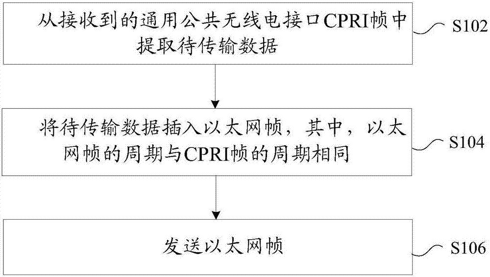
[0065] In this embodiment, a data transmission method is provided, figure 1 is a flow of a data transmission method according to an embodiment of the present invention Figure 1 ,Such as figure 1 As shown, the process includes the following steps:
[0066] Step S102, extracting data to be transmitted from the received CPRI frame;
[0067] Step S104, inserting the data to be transmitted into the Ethernet frame, wherein the period of the Ethernet frame is the same as that of the CPRI frame;
[0068] Step S106, sending the Ethernet frame.
[0069] Optionally, the above data transmission method may be applied, but not limited to, to a scenario covered by a communication network. For example: In the indoor coverage of the communication network, the interface network cable for transmitting Ethernet frames is connected to the optical port of the baseband processing unit.
[0070] Through the above steps, extract the data to be transmitted from the received general public radio i...
Embodiment 2
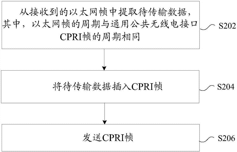
[0088] In this embodiment, a data transmission method is provided, figure 2 is a flow of a data transmission method according to an embodiment of the present invention Figure II ,Such as figure 2 As shown, the process includes the following steps:
[0089] Step S202, extracting data to be transmitted from the received Ethernet frame, wherein the period of the Ethernet frame is the same as that of the CPRI frame;
[0090] Step S204, inserting the data to be transmitted into the CPRI frame;
[0091] Step S206, sending the CPRI frame.
[0092] Optionally, the above data transmission method may be applied, but not limited to, to a scenario covered by a communication network. For example: In the indoor coverage of the communication network, the interface network cable for transmitting Ethernet frames is connected to the optical port of the baseband processing unit.
[0093] Through the above steps, the data to be transmitted is extracted from the received Ethernet frame, wh...
Embodiment 3
[0100]In this embodiment, a data transmission device is also provided, which is used to implement the above embodiments and preferred implementation modes, and what has already been described will not be repeated. As used below, the term "module" may be a combination of software and / or hardware that realizes a predetermined function. Although the devices described in the following embodiments are preferably implemented in software, implementations in hardware, or a combination of software and hardware are also possible and contemplated.
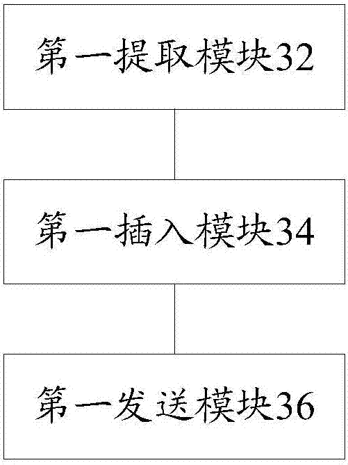
[0101] image 3 is a structural frame of a data transmission device according to an embodiment of the present invention Figure 1 ,Such as image 3 As shown, the device includes:
[0102] The first extraction module 32 is used to extract the data to be transmitted from the received General Public Radio Interface CPRI frame;
[0103] The first insertion module 34, coupled to the first extraction module 32, is used to insert the data to be ...
PUM
 Abstract
Description
Claims
Application Information
 - R&D
- Intellectual Property
- Life Sciences
- Materials
- Tech Scout
- Unparalleled Data Quality
- Higher Quality Content
- 60% Fewer Hallucinations
Browse by: Latest US Patents, China's latest patents, Technical Efficacy Thesaurus, Application Domain, Technology Topic, Popular Technical Reports.
© 2025 PatSnap. All rights reserved.Legal|Privacy policy|Modern Slavery Act Transparency Statement|Sitemap|About US| Contact US: help@patsnap.com