Network device and physical layer address allocation method

A network device and address technology, applied in the field of communication, can solve problems such as access conflicts

Active Publication Date: 2018-01-05
NEW H3C SECURITY TECH CO LTD
View PDF10 Cites 3 Cited by
  • Summary
  • Abstract
  • Description
  • Claims
  • Application Information

AI Technical Summary

Problems solved by technology

In this case, when the Switch chip is connected to multiple expansion cards of the same

Method used


Image

  • Network device and physical layer address allocation method
  • Network device and physical layer address allocation method
  • Network device and physical layer address allocation method

Examples


Embodiment Construction

[0023] The following will clearly and completely describe the technical solutions in the embodiments of the present invention with reference to the accompanying drawings in the embodiments of the present invention. Obviously, the described embodiments are only some, not all, embodiments of the present invention. Based on the embodiments of the present invention, all other embodiments obtained by persons of ordinary skill in the art without making creative efforts belong to the protection scope of the present invention.

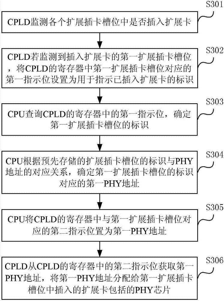
[0024] In order to avoid access conflicts, the invention provides a network device and a PHY address allocation method based on the network device. The present invention will be described in detail below through specific examples.

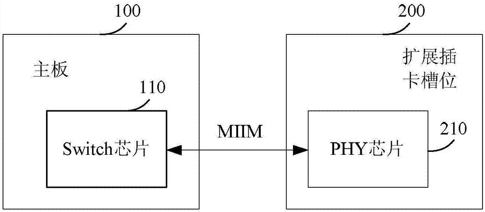
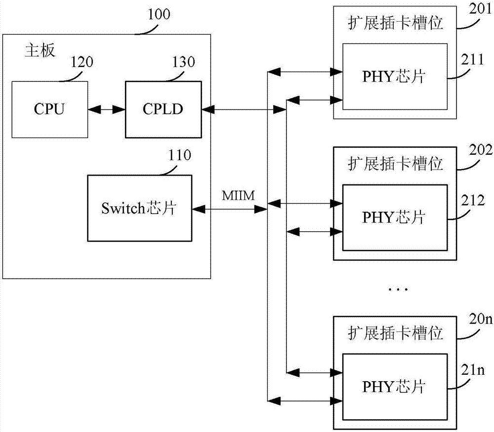
[0025] refer to figure 2 , figure 2 A schematic structural diagram of a network device provided by an embodiment of the present invention, the network device includes: a main board 100 and a plurality of expansion card slots, t...


PUM


Abstract

The embodiment of the invention provides a network device and a physical layer address allocation method. The network device comprises a CPU, a CPLD and a plurality of expansion card slot positions; the CPLD monitors whether expansion cards are inserted in the expansion card slot positions, a first indicating position corresponding to the first expansion card slot position with an inserted expansion card in a register of the CPLD is set as an identifier used for indicating that the expansion card has been inserted; the CPU determines the identifier of the first expansion card slot position, determines a first PHY address corresponding to the identifier of the first expansion card slot position according to a pre-stored corresponding relation between the identifier of the first expansion card slot position and the PHY address, and sets a second indicating position corresponding to the first expansion card slot position in the CPLD as the first PHY address; and the CPLD obtains the firstPHY address from the register and allocates the first PHY address to a PHY chip contained in the expansion card inserted in the first expansion card slot position.

Description

technical field [0001] The invention relates to the technical field of communication, in particular to a method for allocating network equipment and physical layer addresses. Background technique [0002] In order to improve the port density and the flexibility of port type configuration, network devices often provide external expansion card slots, and the expansion card slots provide external ports, thereby realizing on-demand configuration of port types. Such as figure 1 As shown, the network device includes a mainboard 100 and an expansion card slot 200. The mainboard 100 is provided with a Switch (exchange) chip 110, and an expansion card can be inserted in the expansion card slot 200. The expansion card includes a PHY (Physical Lay, physical layer) chip 210. Here, the expansion card containing the PHY chip 210 can provide one or more ports externally; the Switch chip 110 manages the PHY chip 210 through the MIIM (Medium Independent Interface Management, Media Independ...

Claims


Application Information

Patent Timeline
IPC IPC(8): H04L29/12
Inventor 祁超
Owner NEW H3C SECURITY TECH CO LTD
Why Eureka
Try Eureka