Piezoelectric driving brake

A piezoelectric drive and brake technology, applied in the field of vehicles, can solve the problems affecting the braking effect, achieve the effect of improving the braking response time, ensuring driving safety, and providing the braking response time

Inactive Publication Date: 2018-01-09
JIANGSU UNIV OF TECH
View PDF7 Cites 8 Cited by
  • Summary
  • Abstract
  • Description
  • Claims
  • Application Information

AI Technical Summary

Problems solved by technology

However, because of the hydraulic system, when the sealing effect of the sealing ring in the parts is poor, the braking effect will be ...

Method used


Image

  • Piezoelectric driving brake
  • Piezoelectric driving brake

Examples


Embodiment Construction

[0016] Embodiments of the present invention will now be described in detail with reference to the accompanying drawings.

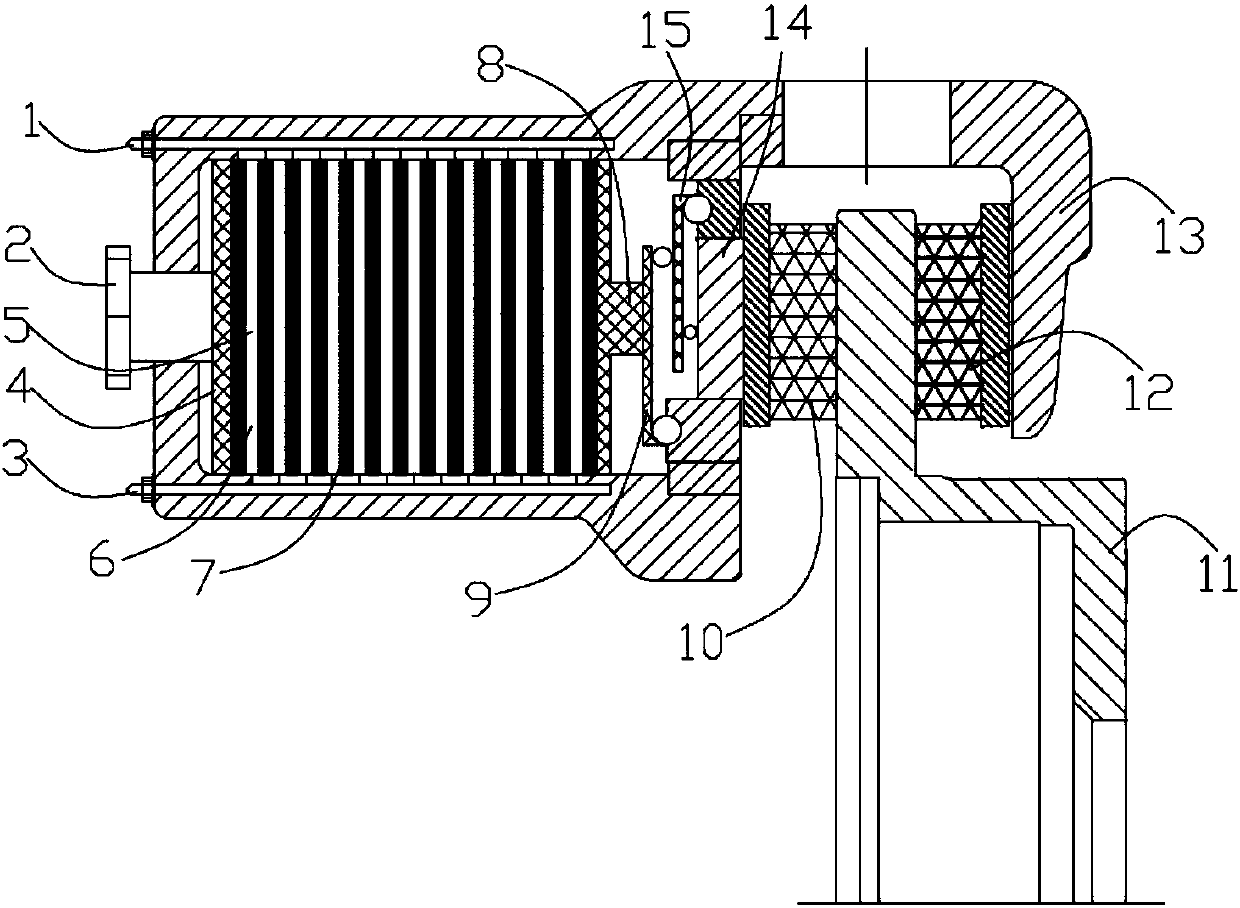
[0017] refer to figure 1 As shown, the present invention provides a piezoelectric-driven brake, which includes a positive terminal 1, a negative terminal 3, a piezoelectric assembly 5, a first end surface 4 located outside the piezoelectric assembly 5, and a The second end surface 8, the displacement amplification mechanism, the inner brake friction plate 10, the outer brake friction plate 12, the gap adjustment bolt 2 for adjusting the gap between the inner brake friction plate 10 and the outer brake friction plate 12, and the floating brake caliper shell Body 13. The piezoelectric assembly 5 includes alternately arranged piezoelectric negative electrode layers 6 connected to the positive electrode 1 of the terminal and piezoelectric positive electrode layers 7 connected to the negative electrode 3 of the terminal. After electrification, the piezoelectri...


PUM


Abstract

The invention provides a piezoelectric driving brake comprising a wiring column positive electrode, a wiring column negative electrode, a piezoelectric assembly, a first end face located on the outerside of the piezoelectric assembly, a second end face located on the inner side of the piezoelectric assembly, a displacement enlarging mechanism, an inner brake friction piece, an outer brake friction piece, a gap adjusting bolt for adjusting the gap between the inner brake friction piece and the outer brake friction piece and a floating type brake clamp shell. The piezoelectric assembly comprises a piezoelectric negative electrode layer connected with the wiring column positive electrode and a piezoelectric positive electrode layer connected with the wiring column negative electrode, whereinthe piezoelectric negative electrode layer and the piezoelectric positive electrode layer are alternately arranged. After being powered-on, the piezoelectric assembly moves to deform, so that the gapbetween the inner brake friction piece and the outer brake friction piece is decreased, and the displacement deformation of the piezoelectric assembly is enlarged through the displacement enlarging mechanism. According to the piezoelectric driving brake, car brake adjustment can be achieved, the brake response time is prolonged, the travelling safety of a car is ensured, and meanwhile the gap between the inner brake friction piece and the outer brake friction piece can be adjusted.

Description

technical field [0001] The invention relates to a piezoelectric driven brake, which belongs to the technical field of vehicles. Background technique [0002] At present, the braking system on the car mainly adopts hydraulic braking, and cooperates with ABS or ESP to ensure the stability of the vehicle during braking and anti-lock braking. The braking system is mainly composed of brake pedal, brake switch, brake master cylinder, vacuum booster, ABS / ESP control unit, brake, wheel speed sensor, hydraulic pipeline, etc. Its advantages are mature technology, reliable performance and high penetration rate. However, because of the hydraulic system, when the sealing effect of the sealing ring in the parts is poor, the braking effect will be affected; in addition, when the emergency braking ABS / ESP works, the response time of its electro-hydraulic control is particularly important. Contents of the invention [0003] The purpose of the present invention is to provide a piezoelectr...

Claims


Application Information

Patent Timeline
IPC IPC(8): B60T8/17B60T8/1755B60T8/58
Inventor 倪彰贝绍轶张兰春李波胡淳
Owner JIANGSU UNIV OF TECH
Why Eureka
Try Eureka