Air floating platform

An air flotation platform and air flotation technology, which is applied in the directions of transportation, packaging, conveyors, etc., can solve the problems of uneven wind thrust, affect the plate pushing effect, and the air flotation ball cannot rotate well, and achieve the effect of good rotation effect.

Pending Publication Date: 2018-01-09
浙江云峰莫干山家居用品有限公司
View PDF9 Cites 7 Cited by
  • Summary
  • Abstract
  • Description
  • Claims
  • Application Information

AI Technical Summary

Problems solved by technology

Existing air floating platforms usually directly use a powerful fan to blow the air floating balls in a suspended state. Since there are multiple air floating balls on the platen, each air floating ball directly receives the wind sent by the powerful fan, and there will be some problems. The thrust of the wind is not uniform. At the same time, the air float ball rotates at the opening of the accommodation cavity, and there will be a problem that the air float ball cannot rotate well due to the roughness of the opening of the accommodation cavity, which will affect the pushing effect on the plate.

Method used


Image

  • Air floating platform
  • Air floating platform
  • Air floating platform

Examples


Embodiment Construction

[0019] The present invention will be further described below in conjunction with the accompanying drawings and embodiments, but not as a basis for limiting the present invention.

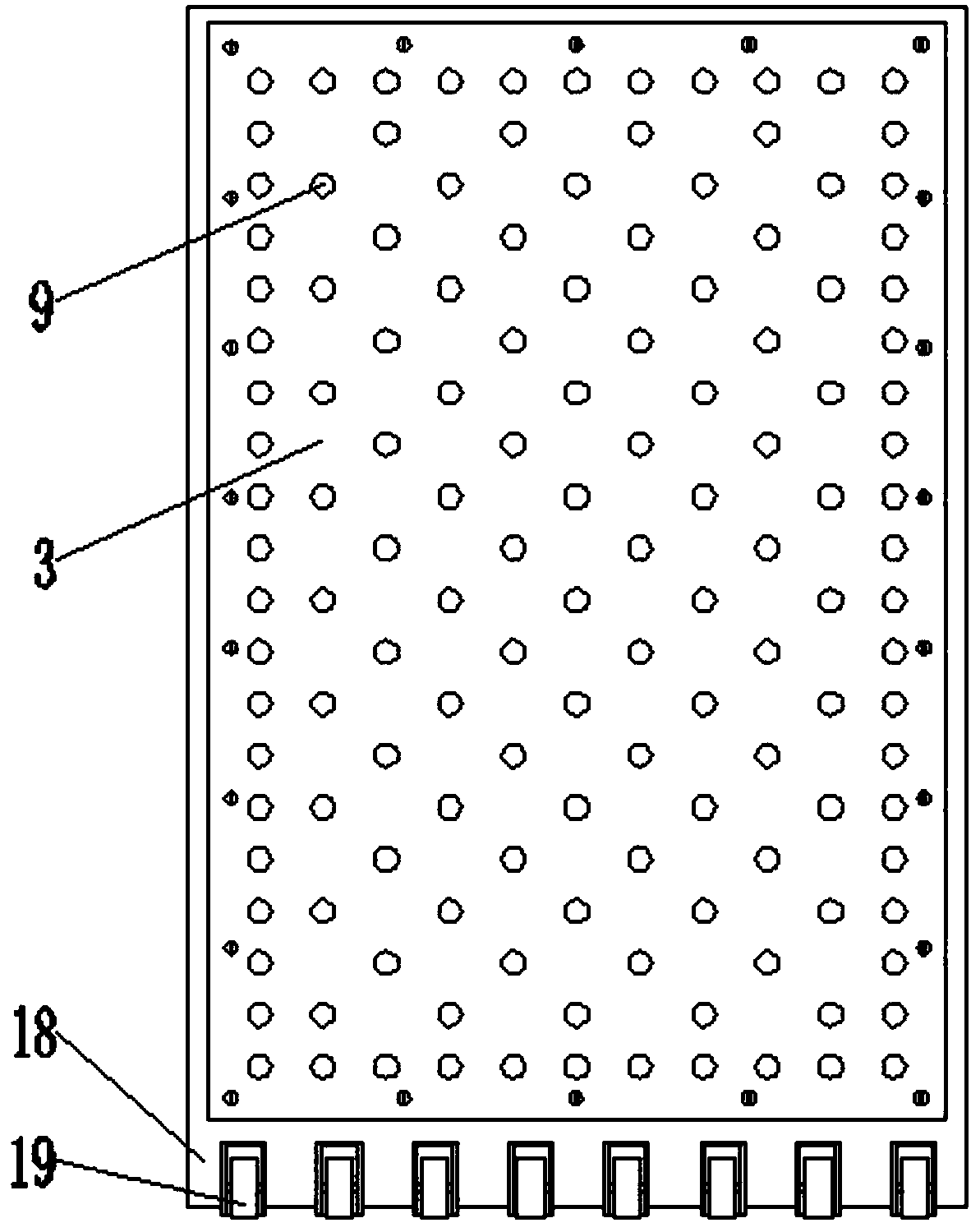
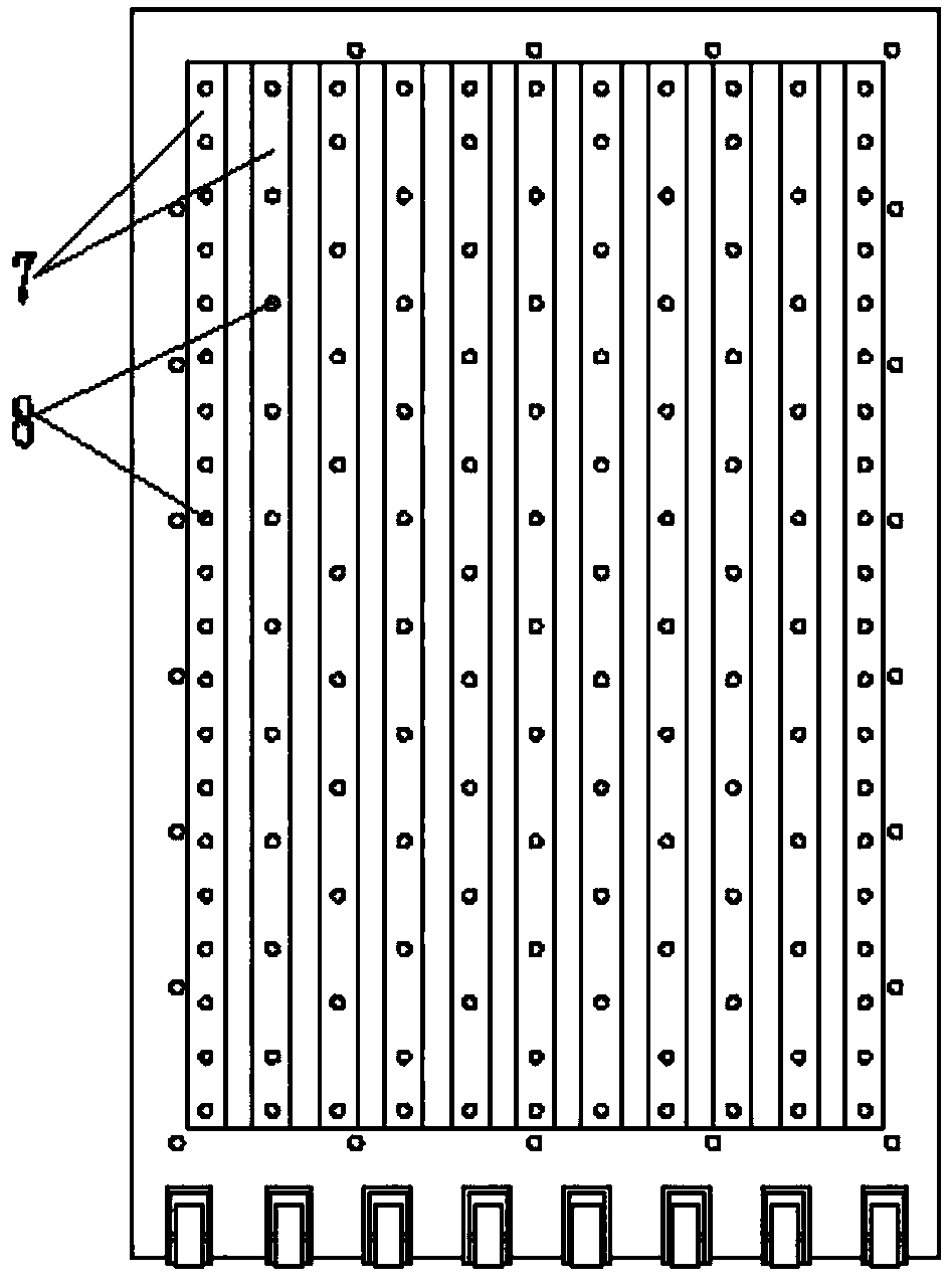
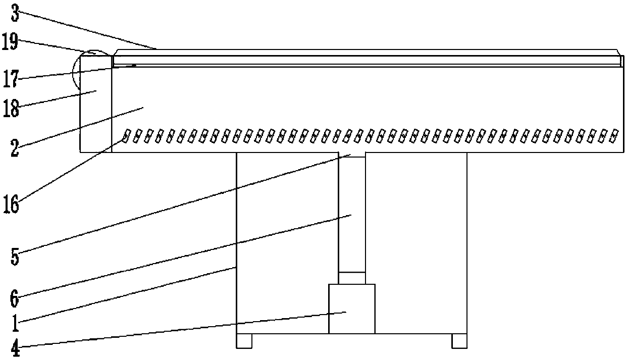
[0020] Such as figure 1 and figure 2 Air floatation platform as shown, including such as image 3 The bracket shown in 1, such as Figure 4 As shown in the buffer chamber 2 and the platen 3, the fan 4 is fixed on the bottom of the bracket, the buffer chamber is fixed on the top of the bracket, the bottom of the buffer chamber is provided with an air inlet 5, and the air inlet is connected to the outlet of the fan through the connecting pipe 6. The air outlet is connected, the connecting pipe is a telescopic pipe, and the telescopic pipe is threadedly connected to the air inlet and the air outlet of the fan. The top of the buffer chamber is fixed with a number of protruding first air ducts 7 side by side. The first air duct and the buffer chamber The transitional joints are all rounded, and there...


PUM


Abstract

The invention relates to the technical field of plate conveying equipment, in particular to an air floating platform. The air floating platform comprises a bracket, a buffer cavity and a table plate.The bracket is provided with a fan. An air inlet is formed in the bottom of the buffer cavity. The air inlet is connected with a wind outlet of the fan through a connecting pipe. The top of the buffercavity is provided with a plurality of first wind ducts side by side. A plurality of first air outlets are formed in the top of each first wind duct. The table plate is arranged at the top of the buffer cavity. An air floating unit is arranged at the position, corresponding to the first air outlets, of the table plate. The air floating unit comprises a second wind duct, a storing cavity and an air floating ball. The air floating ball is located in the storing cavity. An opening of the top of the storing cavity forms a second air outlet. At least three spherical cavities are formed in the inner wall, close to the top opening, of the storing cavity. Rolling beads are arranged in the spherical cavities. Parts of the rolling beads protrude out of the spherical cavities and are located in thestoring cavity. The air floating platform has the characteristics that stress of the air floating ball is uniform, the air floating ball can well rotate, and the efficiency of conveying plates is high.

Description

technical field [0001] The invention relates to the technical field of plate conveying equipment, in particular to an air floating platform. Background technique [0002] The front-loading electronic cutting saws used in the existing sheet metal processing usually use an air-floating platform to feed the sheet. The basic working principle of the air-floating platform is to use the pressure wind sent by a powerful fan to push the air-floating ball on the platen to a suspended state. , the air float ball can rotate in the accommodating chamber where it is located, and through the rotation of several air float balls, the plate on the platen can be easily pushed into the electronic cutting saw for cutting. Existing air floating platforms usually directly use a powerful fan to blow the air floating balls in a suspended state. Since there are multiple air floating balls on the platen, each air floating ball directly receives the wind sent by the powerful fan, and there will be som...

Claims


Application Information

Patent Timeline
Patent Type & Authority Applications(China)
IPC IPC(8): B65G51/02
Inventor 唐远明张江费建良蔡伟于克徐东辉
Owner 浙江云峰莫干山家居用品有限公司
Why Eureka
Try Eureka