
Linear valve drive and valve

一种直线驱动器、驱动器的技术,应用在仪器、隔膜阀、阀装置等方向,能够解决不能补偿使用寿命效果等问题

Active Publication Date: 2018-01-09
BURKERT WERKE
View PDF11 Cites 3 Cited by
  • Summary
  • Abstract
  • Description
  • Claims
  • Application Information

AI Technical Summary

Problems solved by technology

However, this does not compensate for the resulting service life effect

Method used


Image

  • Linear valve drive and valve
  • Linear valve drive and valve
  • Linear valve drive and valve

Examples


Embodiment Construction

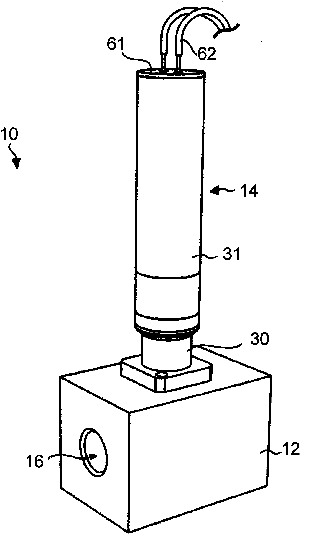
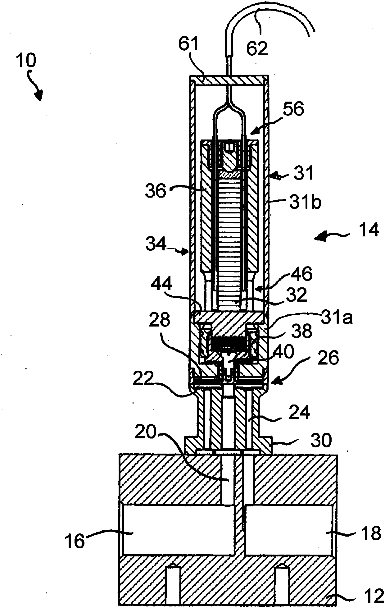
[0037] exist figure 1 and figure 2 A valve 10 is shown in , which is used to control or regulate a fluid. In the embodiment shown, the valve 10 is constructed in two parts and comprises a valve body 12 and a valve linear drive 14 coupled thereto.

[0038] The valve body 12 has a fluid inlet 16 via which the fluid to be controlled or regulated is supplied to the valve 10 . Furthermore, the valve body 12 has a fluid outlet 18 via which fluid can leave the valve 10 .

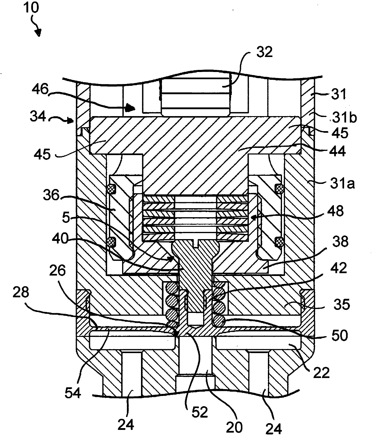
[0039] Also formed in the valve body 12 is an inflow channel 20 which is in flow connection with the fluid inlet 16 . The inflow channel 20 opens into a collecting space 22 , which in turn forms a flow connection with two outflow channels 24 , which open into the fluid outlet 18 .

[0040] The valve body 12 is formed in particular from a corrosion-resistant material. In particular, the inner sides of the fluid-conducting channels and spaces consist of a corrosion-resistant material.

[0041] Furthermore, a v...


PUM


Abstract

A linear valve drive for connection to a valve body which has a valve seat is described, wherein said linear valve drive comprises a drive housing, a valve closure element and a piezoelectric actuatorwhich is arranged within said drive housing. Said valve closure element is displaceable in the axial direction between an open position and a closed position by means of said piezoelectric actuator and an interposed actuating device. Said piezoelectric actuator is supported on said actuating device via its side directed towards the valve closure element. Said linear valve drive comprises an adjusting device which is configured such that an idle stroke of said linear valve drive is adjustable. A valve is also described.

Description

technical field [0001] The invention relates to a valve linear drive for connection to a valve body, which has a valve seat, and to a valve, in particular a hydraulically actuated valve, ie a normally closed valve (NC valve). Background technique [0002] Valves for controlling or regulating fluids are known from the prior art which have a valve body and a valve linear drive which is formed separately from the valve body. The valve linear actuator and the valve body are connected to each other so as to constitute a valve. [0003] The valve linear drive has a drive unit, for example a piezoelectric actuator. The drive unit can adjust the valve locking element via an actuating device or an actuating mechanism arranged in the valve linear drive. In this way, the valve linear drive can move the valve closure element at least into the open position and / or into the closed position, wherein the valve closure element rests against a valve seat formed in the valve body and seals t...

Claims


Application Information

Patent Timeline
Patent Type & Authority Applications(China)
IPC IPC(8): F16K31/04F16K7/14H10N30/02H10N30/50H10N30/88
CPCF16K31/007Y10T137/7761F16K31/008G05D7/0635H10N30/02H10N30/50H10N30/88F16K31/004
Inventor 迈克尔·舒普扬·韦斯特曼
Owner BURKERT WERKE
Features
  • Generate Ideas
  • Intellectual Property
  • Life Sciences
  • Materials
  • Tech Scout
  • Unparalleled Data Quality
  • Higher Quality Content
  • 60% Fewer Hallucinations
Learn More