Track lamp

A track light and track technology, which is applied to the loss prevention measures of lighting devices, lighting and heating equipment, lighting devices, etc. Short and other problems, to achieve stable and reliable connection and electrical contact, improve light output, and eliminate the effect of dark areas

Active Publication Date: 2018-01-09
TOBI LED
View PDF6 Cites 4 Cited by
  • Summary
  • Abstract
  • Description
  • Claims
  • Application Information

AI Technical Summary

Problems solved by technology

[0003] Existing track lights generally include a guide rail body and a lamp body. The guide rail body is provided with a U-shaped groove, and the two opposite inner walls of the U-shaped groove are provided with installation grooves for installing bare wires. The lamp body is provided with a PCB board, and the two sides of the PCB board Elastic connection terminals are respectively provided on both sides of the end close to the two bare wires. When the lamp body is pressed down and inserted into the top of the guide rail body, the connection terminals are elastically deformed and closely abut against the bare wires, such as the invention with the publication number CN205592721U Patent, because the lamp body and the guide rail body are clamped and fixed only by the elastic force of the connecting terminal, the connection and electrical contact reliability between the lamp body and the guide rail body is poor, and it is easy to be caused by installation processing errors or vibrations. As a result, the electrical contact is poor, and even the lamp body falls off from the guide rail body
At the same time, the creepage distance between the two bare wires on the guide rail body is short, which is not suitable for high-voltage lamp bodies, and the application range is limited

Method used


Image

  • Track lamp
  • Track lamp
  • Track lamp

Examples


Embodiment Construction

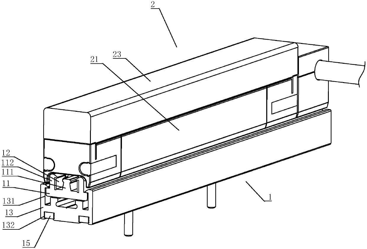
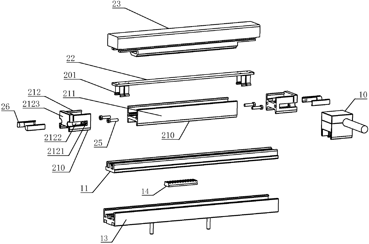
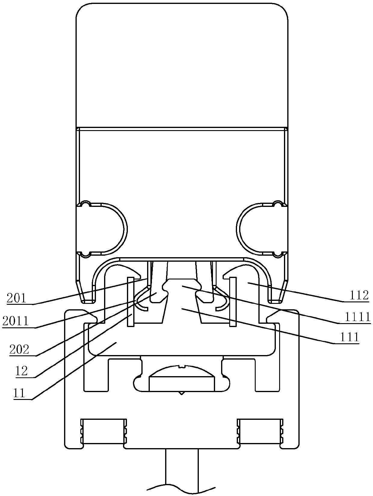
[0030] refer to Figure 1 to Figure 8 , a track light provided by the present invention includes a track part 1 and at least one lamp body module 2 installed on the track part 1, the track part 1 includes a guide rail part 11, and a track electrode 12 arranged on the guide rail part 11 , one end of the guide rail part 11 is provided with a power supply connection part 10 electrically connected to the track electrode 12 for supplying power to the guide rail part 11, and the guide rail part 11 is provided with an electrode isolation part 111 between the track electrodes 12, the electrode The isolation part 111 separates the track electrode 12 and increases the creepage distance, thereby improving the working voltage and safety of the track light. The end of the electrode isolation part 111 close to the lamp body module 2 is provided with a fastening part 1111, and the lamp body module 2 is provided with a connecting terminal 201 electrically connected to the track electrode 12, ...


PUM


Abstract

The invention discloses a track lamp. The track lamp comprises a track part and at least one lamp body module arranged on the track part, the track part comprises a guide rail part and track electrodes arranged on the guide rail part, the lamp body module is provided with connecting terminals electrically connected with the track electrodes, an electrode isolation part is arranged at the position,between the track electrodes, of the guide rail part, the end, close to the lamp body module, of the electrode isolation part is provided with a buckling part, elastic buckles matched with the buckling part are arranged on the lamp body module, the connecting terminals are arranged on the outer sides of the elastic buckles, when the elastic buckles and the buckling part are combined, elastic deformation is generated, and therefore the connecting terminals and the track electrodes are tightly in abut joint. A connecting structure between the lamp module and the track part is sufficiently usedfor reinforcing electric contact between the track electrodes and the lamp module, reliability is improved while the structure is simplified, the lamp body module can be pressed in the track part in place in a one-time operation manner, and mounting is more convenient and rapid.

Description

technical field [0001] The invention relates to a lighting device, in particular to a track light. Background technique [0002] Track light is a lighting device that installs lamps on the track. In addition to providing lighting, it can also be used flexibly according to various needs of users to form different decorative effects. Therefore, it is widely used in shopping malls and exhibition halls. , hotels and other places. [0003] Existing track lights generally include a guide rail body and a lamp body. The guide rail body is provided with a U-shaped groove, and the two opposite inner walls of the U-shaped groove are provided with installation grooves for installing bare wires. The lamp body is provided with a PCB board, and the two sides of the PCB board Elastic connection terminals are respectively provided on both sides of the end close to the two bare wires. When the lamp body is pressed down and inserted into the top of the guide rail body, the connection terminal...

Claims


Application Information

Patent Timeline
Patent Type & Authority Applications(China)
IPC IPC(8): F21S8/00F21V19/00F21V21/34F21V23/06F21V17/16F21V5/00
CPCF21S8/00F21V15/015F21V17/16F21V21/35F21V23/06
Inventor 黄云崧杨家良
Owner TOBI LED
Why Eureka
Try Eureka