Pressure touch structure and display device

A pressure and heat dissipation structure technology, applied in the direction of instruments, electrical digital data processing, electrical components, etc., can solve the problems of poor pressure touch effect, uneven Cu heat sink, and increased material cost, so as to reduce the bonding process and reduce the Material cost, effect of improving pressure touch effect

Active Publication Date: 2018-01-09
BOE TECH GRP CO LTD
View PDF12 Cites 0 Cited by
  • Summary
  • Abstract
  • Description
  • Claims
  • Application Information

AI Technical Summary

Problems solved by technology

The pressure touch effect is poor due to the unevenness of the Cu heat sink
In addition, the separate setting of Cu heat sink adds a bonding process and increases the cost of materials

Method used


Image

  • Pressure touch structure and display device
  • Pressure touch structure and display device
  • Pressure touch structure and display device

Examples


Embodiment Construction

[0021] In order to make those skilled in the art better understand the technical solutions of the present invention, the pressure touch control structure and the display device provided by the present invention will be described in detail below with reference to the accompanying drawings.

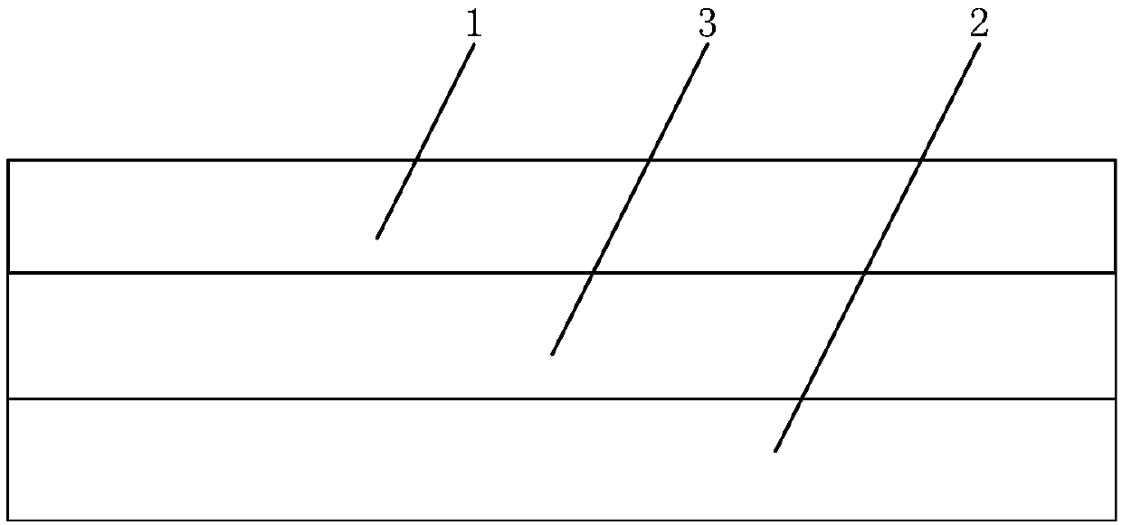
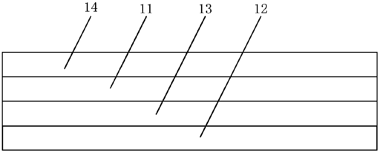
[0022] figure 1 It is a schematic structural diagram of a pressure touch structure provided in Embodiment 1 of the present invention, figure 2 for figure 1 The structure diagram of the medium pressure sensor, such as figure 1 and figure 2 As shown, the pressure touch structure includes: a pressure sensor 1 and a reference layer 2, a capacitance is formed between the pressure sensor 1 and the reference layer 2, the pressure sensor 1 includes a first pattern layer 11 and a second pattern layer, and the second pattern layer includes Heat dissipation structure 12 .

[0023] In this embodiment, the pressure touch structure can be applied to a display device. The display device is provided ...


PUM


Abstract

The invention discloses a pressure touch structure and a display device. The pressure touch structure comprises a pressure sensor and a reference layer, wherein capacitance is formed between the pressure sensor and the reference layer; the pressure sensor comprises a first pattern layer and a second pattern layer, and the second pattern layer comprises a cooling structure. In the pressure touch structure, the cooling structure is arranged in the pressure sensor, cooling fins do not need to be independently arranged except the pressure sensor, the problem of poor pressure touch effect caused bythe unevenness of the cooling fin is avoided, and therefore, a pressure touch effect is improved. Since the cooling fins do not need to be independently arranged except the pressure sensor, a fittingtechnology that the cooling fins are independently arranged is omitted, and material cost is lowered.

Description

technical field [0001] The present invention relates to the field of display technology, and in particular, to a pressure touch control structure and a display device. Background technique [0002] With the development of touch technology, capacitive force touch technology is increasingly used in display devices. For the display device provided with the capacitive pressure touch structure, different control functions can be triggered by different touch force. [0003] The capacitive pressure touch structure in the prior art may include a force sensor and a reference layer, the reference layer is grounded, an isolation layer is disposed between the pressure sensor and the reference layer, and the force sensor and the reference layer form a capacitor. [0004] The capacitive pressure touch structure also includes a Cu heat sink for heat dissipation. The Cu heat sink is a separate structure in the capacitive pressure touch structure. Due to the unevenness of the Cu heat sink...

Claims


Application Information

Patent Timeline
Patent Type & Authority Applications(China)
IPC IPC(8): G06F3/041G06F3/044G06F1/20
CPCG06F3/041G06F3/044G06F2203/04105G06F3/0412H01L33/64H05K1/189
Inventor 郑美珠
Owner BOE TECH GRP CO LTD
Why Eureka
Try Eureka