Pull switch

A pull-type, switch technology, applied in the direction of electric switches, electrical components, circuits, etc., can solve the problems of safety hazards of power-on switches, tripping, and the wires of electrical equipment falling on the ground.

Active Publication Date: 2018-01-09
RUGAO LANTU KNITTING CLOTHING CO LTD
View PDF5 Cites 2 Cited by
  • Summary
  • Abstract
  • Description
  • Claims
  • Application Information

AI Technical Summary

Problems solved by technology

[0003] The current power-on switch generally directly connects the interface of the electrical equipment to the socket, and the wires of the electrical equipment generally hang down on the ground. This non-enclosed power-on method is not only easy to be touched by children, but also very It is easy to cause safety accidents due to accidental splashing of water, and it is easy for people to trip over the wires of electrical appliances hanging on the ground. Many people have the habit of not unplugging the plug when they sleep, which makes the current power switch have many safety hazards.
[0004] Therefore urgently need to develop a kind of closed type, open the power-on switch by pull cord and the pull-type switch that can not drop the line of electrical equipment on the ground, to overcome non-closed type in the prior art, open power-on switch by socket The disadvantage that the wires of electrical equipment will hang down on the ground

Method used


Image

  • Pull switch
  • Pull switch
  • Pull switch

Examples


Embodiment 1

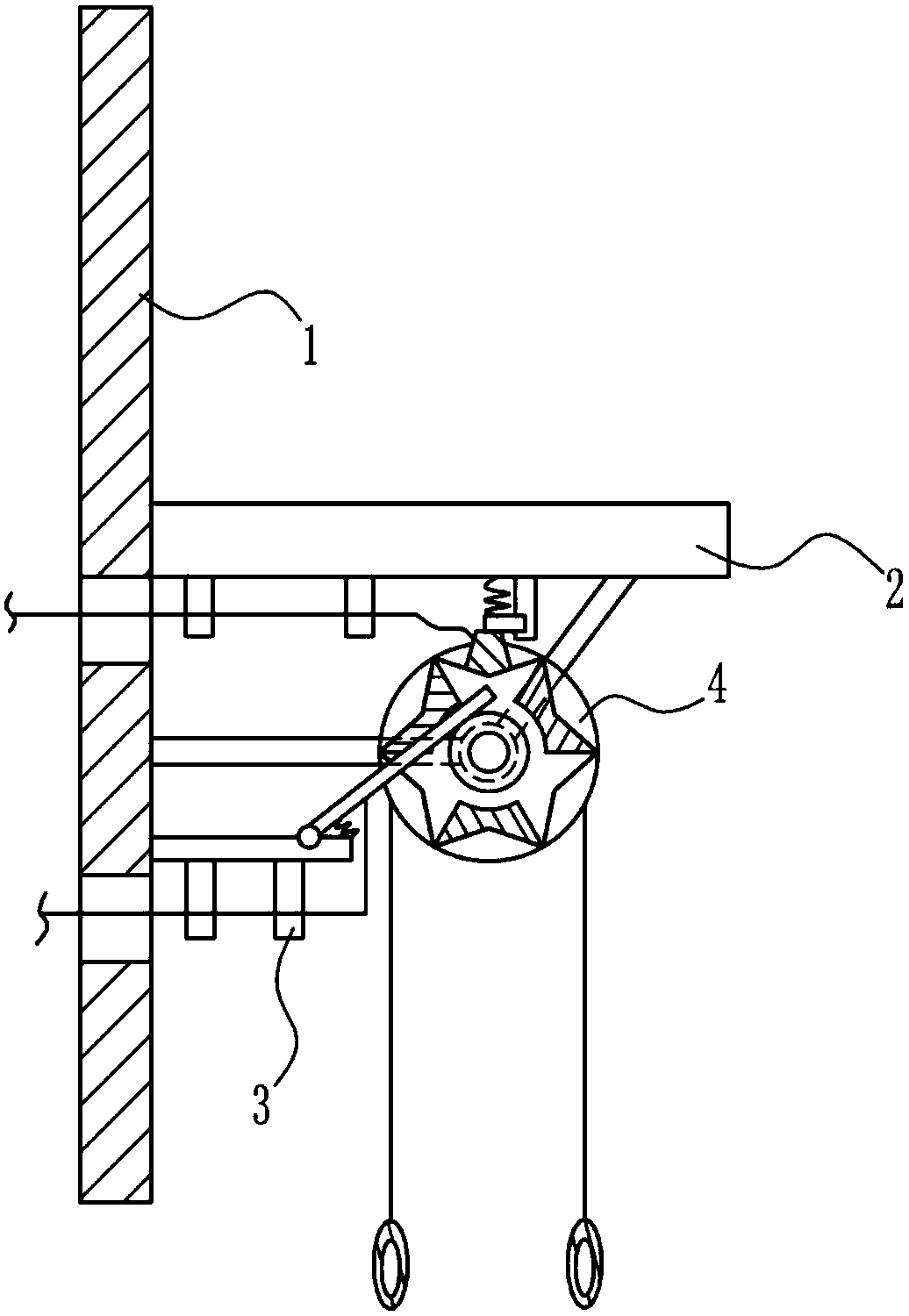
[0035] A pull switch such as Figure 1-7 As shown, it includes a mounting plate 1, a first connecting rod 2, a connecting mechanism 3 and a rotating mechanism 4, the right side of the mounting plate 1 is connected with the first connecting rod 2, the right side of the mounting plate 1 is connected with the connecting mechanism 3, and the first connecting The rod 2 is located on the upper side of the connecting mechanism 3 , and the bottom of the first connecting rod 2 is connected with a rotating mechanism 4 .

Embodiment 2

[0037] A pull switch such as Figure 1-7 As shown, it includes a mounting plate 1, a first connecting rod 2, a connecting mechanism 3 and a rotating mechanism 4, the right side of the mounting plate 1 is connected with the first connecting rod 2, the right side of the mounting plate 1 is connected with the connecting mechanism 3, and the first connecting The rod 2 is located on the upper side of the connecting mechanism 3 , and the bottom of the first connecting rod 2 is connected with a rotating mechanism 4 .

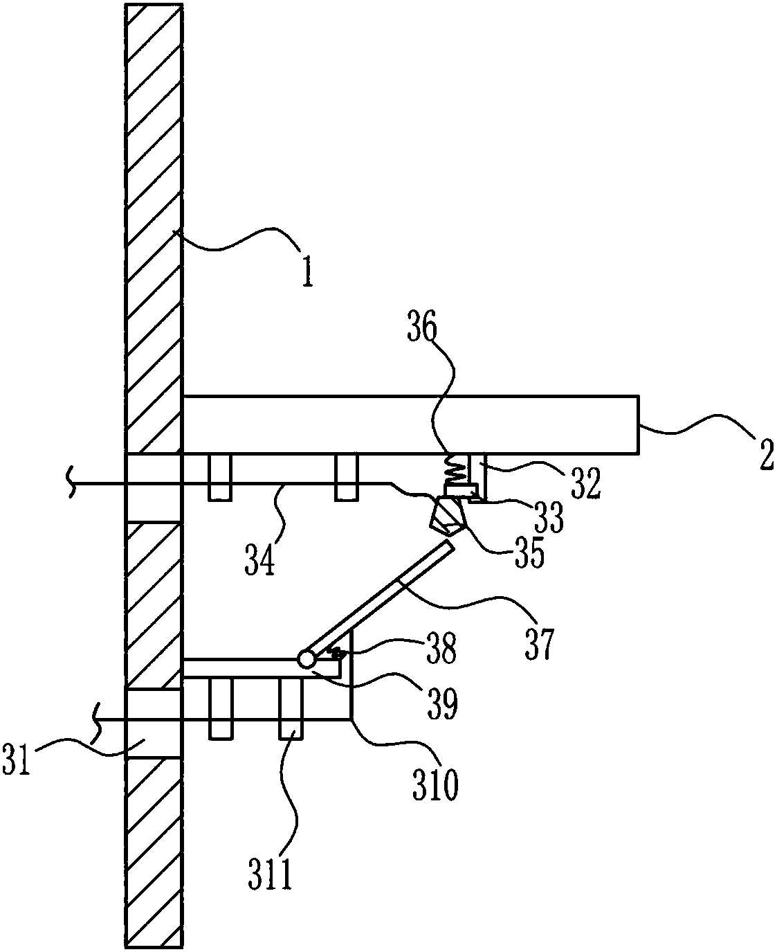
[0038] The connection mechanism 3 includes a first slide rail 32, a first slider 33, a first electric wire 34, a copper block 35, a first spring 36, a conductive rod 37, a second spring 38, a second connecting rod 39, and a second electric wire 310 With the first fixed rod 311, the bottom of the mounting plate 1 is symmetrically opened with the first through hole 31 up and down, the right wall of the mounting plate 1 is connected with the second connecting rod 39, and ...

Embodiment 3

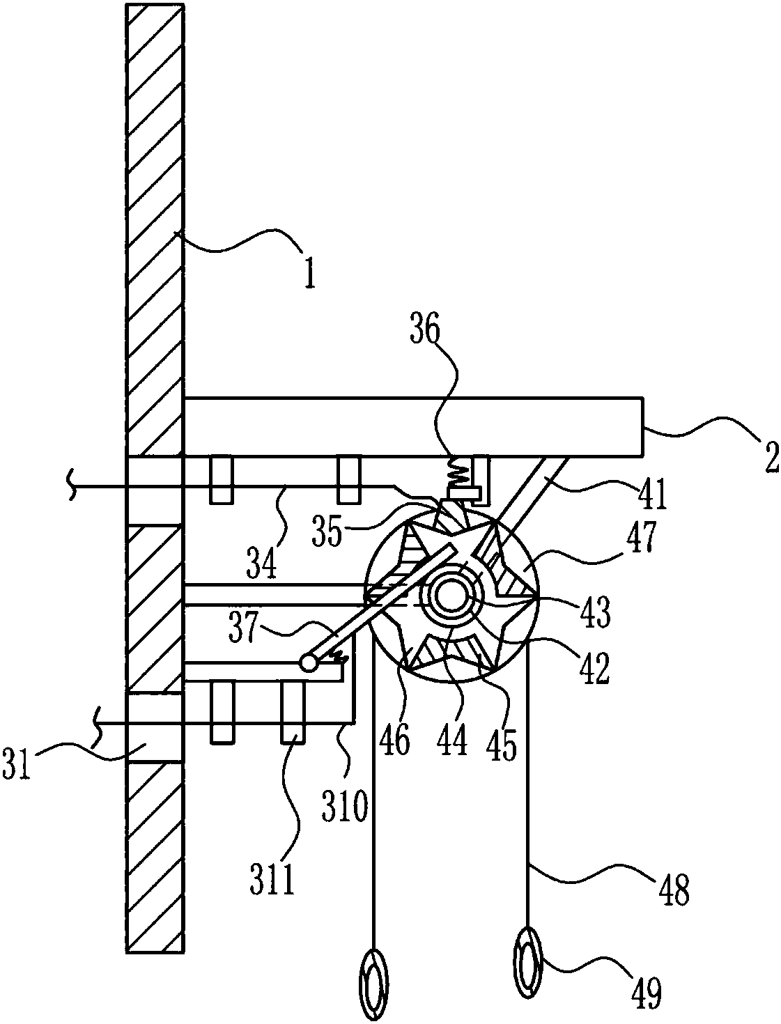
[0040] A pull switch such as Figure 1-7 As shown, it includes a mounting plate 1, a first connecting rod 2, a connecting mechanism 3 and a rotating mechanism 4, the right side of the mounting plate 1 is connected with the first connecting rod 2, the right side of the mounting plate 1 is connected with the connecting mechanism 3, and the first connecting The rod 2 is located on the upper side of the connecting mechanism 3 , and the bottom of the first connecting rod 2 is connected with a rotating mechanism 4 .

[0041] The connection mechanism 3 includes a first slide rail 32, a first slider 33, a first electric wire 34, a copper block 35, a first spring 36, a conductive rod 37, a second spring 38, a second connecting rod 39, and a second electric wire 310 With the first fixed rod 311, the bottom of the mounting plate 1 is symmetrically opened with the first through hole 31 up and down, the right wall of the mounting plate 1 is connected with the second connecting rod 39, and ...


PUM


Abstract

The invention relates to a switch, and in particular to a pull switch. The pull switch which is closed and is used for starting an energization switch by a pull rope and preventing a line of electrical appliance equipment from falling on ground is provided. In order to solve the technical problem, the pull switch provided by the invention comprises an installation plate, wherein a first connectionrod is arranged at a right side of the installation plate, a connection mechanism is connected with a right side of the installation plate, the first connection rod is arranged at an upper side of the connection mechanism, and a rotation mechanism is connected to the bottom of the first connection rod. With the arrangement of a roller and a copper sheet, electrical appliance can be controlled tobe energized and disconnected only through pulling a first pull rope by a user; with the arrangement of a second baffle plate, a third baffle plate and a top plate, a person is prevented from directlytouching a conductive rod and a conductive contact wheel to cause a safety accident; and with the arrangement of a luminous plate, the user is convenient to find out the device at night or in a placewith dark light so as to make the electrical appliance energized.

Description

technical field [0001] The invention relates to a switch, in particular to a pull switch. Background technique [0002] The word switch is interpreted as on and off. It also refers to an electronic component that can open a circuit, interrupt the current flow, or cause it to flow to other circuits. The most common switches are human-operated electromechanical devices that have one or more electrical contacts. The "closed" of the contact means that the electronic contact is conductive and allows current to flow; the "open circuit" of the switch means that the electronic contact is not conductive to form an open circuit and does not allow current to flow. [0003] The current power-on switch generally directly connects the interface of the electrical equipment to the socket, and the wires of the electrical equipment generally hang down on the ground. This non-enclosed power-on method is not only easy to be touched by children, but also very It is easy to cause safety accide...

Claims


Application Information

Patent Timeline
IPC IPC(8): H01H17/06
Inventor 钟国强朱麒宇朱义正
Owner RUGAO LANTU KNITTING CLOTHING CO LTD
Why Eureka
Try Eureka