Method for acquiring electric capacity of energy-gathering indication battery

A capacity and battery technology, applied in small-sized batteries/battery packs, large-sized batteries/battery packs, secondary batteries, etc. Storage and other issues to achieve the effect of weakening the self-discharge phenomenon and using safe

Inactive Publication Date: 2018-01-09
胡振华
View PDF0 Cites 1 Cited by
  • Summary
  • Abstract
  • Description
  • Claims
  • Application Information

AI Technical Summary

Problems solved by technology

[0003] As a common portable energy storage component, batteries are widely used in various fields, such as batteries in the transportation industry, power boards in the communication industry, small batteries in the toy industry, etc.; because the positive and negative electrodes of the battery are exposed to the air, the battery The surrounding air is ionized to transfer charge, so the battery will inevitably discharge to the outside, so the battery that has been placed for a long time will have a self-discharge phenomenon, and the electric energy stored in the battery cannot be stored for a long time; in addition, the current battery has no clear instructions mark, the actual capacity of the battery cannot be known during use, and therefore the power consumption of the electrical appliance cannot be known; especially disposable batteries cannot make full use of the internal power, and at the same time, a long replacement cycle will affect the normal use of the electrical appliance

Method used


Image

  • Method for acquiring electric capacity of energy-gathering indication battery

Examples


Embodiment

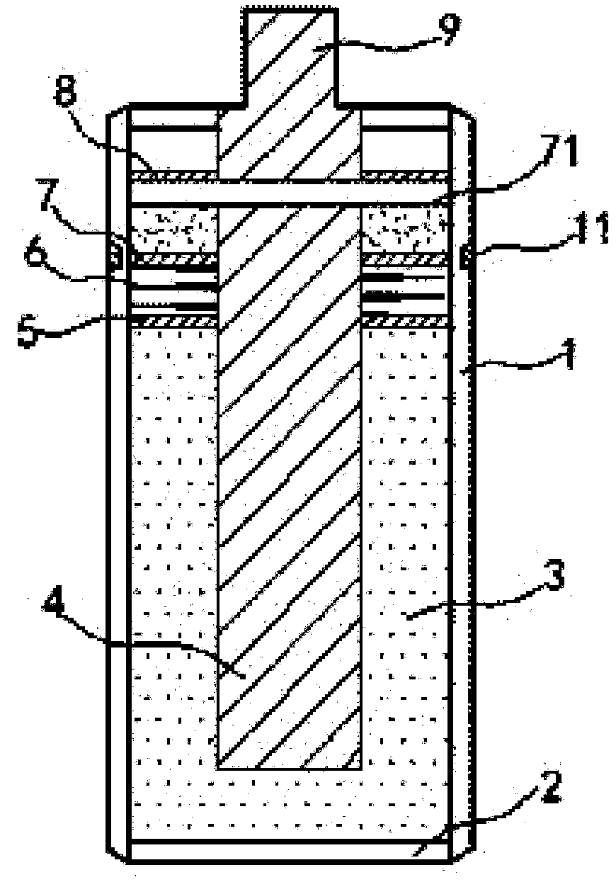
[0014] exist figure 1 In the shown embodiment, the concentrated energy indicating battery includes a housing 1, a negative plate 2, a negative electrode material 3 and a positive pole 4; the positive pole 4 is inserted into the negative pole material 3; the housing 1 is made of a transparent material A sealing plate 5 is installed on the upper surface of the negative electrode material 3; a compression spring 6 is fixed on the sealing plate 5; a liquid seal plate 7 is fixed on the upper end of the compression spring 6, and the liquid seal plate 7 Made of permanent magnetic material, the sealing plate 5 and the liquid sealing plate 7 are both tightly sleeved on the positive pole 4; the upper end of the positive pole 4 is covered with a liquid seal film 71, and the liquid seal Conductive liquid is filled between the film 71 and the liquid seal plate 7; a vacuum plate 8 is fixedly installed in parallel above the liquid seal film 71, and a vacuum is drawn between the vacuum plate ...


PUM


Abstract

The invention relates to a method for acquiring electric capacity of an energy-gathering indication battery. The energy-gathering indication battery comprises a shell, a negative plate, a negative material and a positive pole, wherein a sealing plate is arranged on an upper surface of the negative material; a pressure spring is fixed on the sealing plate; a liquid sealing plate is fixed on the upper end of the pressure spring, and the liquid sealing plate is made of permanent material; the sealing plate and the liquid sealing plate are airtightly sleeved on the positive pole; a liquid sealingfilm is covered on the upper end of the positive pole; conducting liquid is filled between the liquid sealing film and the liquid sealing plate; a vacuum plate is fixedly arranged above the liquid sealing film in parallel, the place between the vacuum plate and the liquid sealing film is vacuumized; a positive end is fixedly inserted into the vacuum plate; and a permanent magnet is arranged at thelocation directly facing the liquid sealing plate at the external of the shell; the battery can effectively prevent the battery from self-discharging, and the battery storage period is effectively prolonged; at the same time, the battery usage situation can be displayed, and the battery usage is more scientific.

Description

[0001] This application relates to a divisional application with the application number 201610002322.9 and the title of the invention is energy-gathering indicating battery. technical field [0002] The invention relates to an energy storage element, especially a battery. Background technique [0003] As a common portable energy storage component, batteries are widely used in various fields, such as batteries in the transportation industry, power boards in the communication industry, small batteries in the toy industry, etc.; because the positive and negative electrodes of the battery are exposed to the air, the battery The surrounding air is ionized to transfer charge, so the battery will inevitably discharge to the outside, so the battery that has been placed for a long time will have a self-discharge phenomenon, and the electric energy stored in the battery cannot be stored for a long time; in addition, the current battery has no clear instructions Mark, the actual capa...

Claims


Application Information

Patent Timeline
Patent Type & Authority Applications(China)
IPC IPC(8): H01M10/42H01M10/48H01M2/02H01M50/10H01M50/116
CPCH01M10/42H01M10/48H01M10/488H01M50/10H01M50/116Y02E60/10
Inventor 胡振华
Owner 胡振华
Why Eureka
Try Eureka